
Magnetic printing equipment and cylindrical magnets

A magnetic printing and columnar technology, applied in printing, printing machines, rotary printing machines, etc., can solve the problems of complex magnet combination and consumption of magnetic materials, and achieve the effects of compact equipment structure, saving magnetic materials, and saving production costs

Active Publication Date: 2020-07-17
HUIZHOU FORYOU OPTICAL TECH
View PDF5 Cites 0 Cited by
  • Summary
  • Abstract
  • Description
  • Claims
  • Application Information

AI Technical Summary

Problems solved by technology

[0004] The invention provides a magnetic printing device and a columnar magnet for magnetically orienting magnetic pigment flakes, which can solve the problems of complex magnet combination and consumption of more magnetic materials in the prior art, so that more can be arranged on a unit printing area. Multiple fixed magnetic units

Method used


Image

  • Magnetic printing equipment and cylindrical magnets
  • Magnetic printing equipment and cylindrical magnets
  • Magnetic printing equipment and cylindrical magnets

Examples


Embodiment Construction

[0013] The following will clearly and completely describe the technical solutions in the embodiments of the present invention with reference to the accompanying drawings in the embodiments of the present invention. Obviously, the described embodiments are only some, not all, embodiments of the present invention. Based on the embodiments of the present invention, all other embodiments obtained by persons of ordinary skill in the art without making creative efforts belong to the protection scope of the present invention.

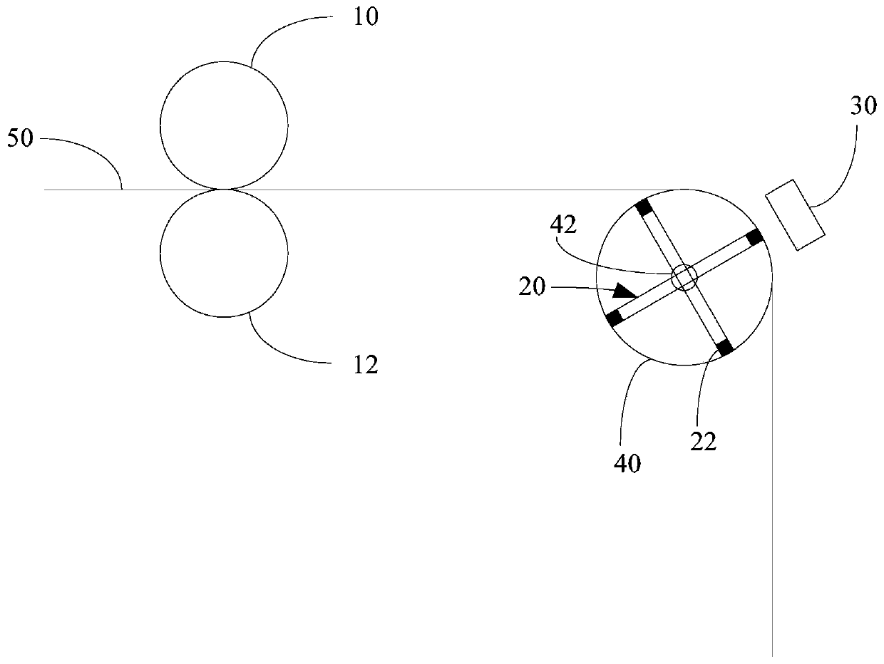
[0014] see figure 1 , figure 1 It is a schematic structural diagram of a magnetic printing device provided by an embodiment of the present invention.

[0015] figure 1 The illustrated magnetic printing apparatus is a roll-to-roll continuous printing apparatus including printing units 10 , 12 , magnetic orientation unit 20 , curing unit 30 and transfer unit 40 .

[0016] Specifically, the transfer device 40 transfers the printed matter substrate 50 through t...


PUM

PropertyMeasurementUnit
sizeaaaaaaaaaa

Abstract

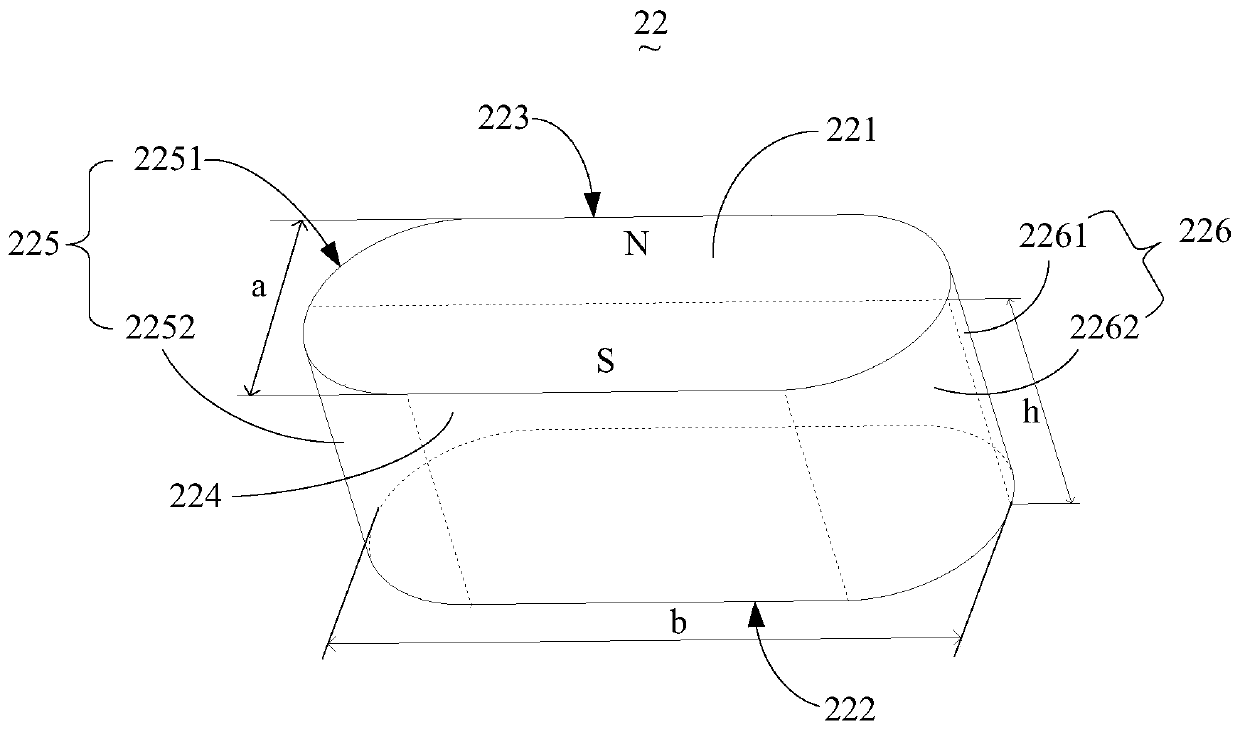
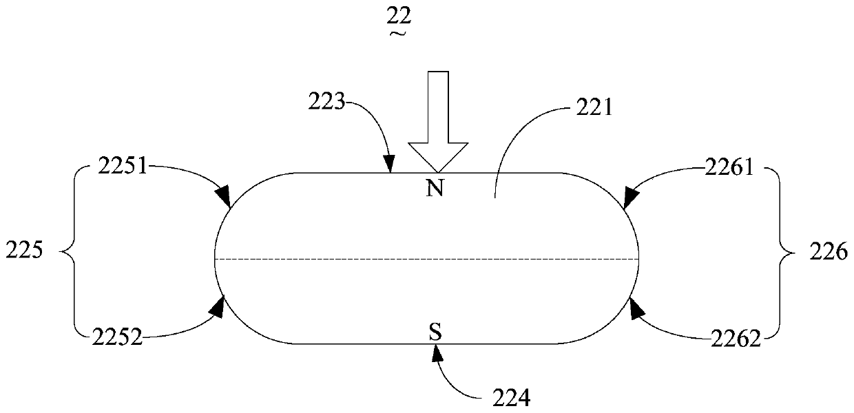
A magnetic printing apparatus and a columnar magnet. The magnetic printing apparatus comprises printing devices (10, 12), a magnetic orientation device (20), and a curing device (30); the magnetic orientation device (20) comprises at least one columnar magnet (22); the columnar magnet (22) comprises a first end surface (221) and a second end surface (222) disposed oppositely, and multiple side surfaces that are separately connected to the first end surface (221) and the second end surface (222); the multiple side surfaces comprise a first side surface (223) and a second side surface (224) that are disposed oppositely and are flat surfaces, as well as a third side surface (225) and a fourth side surface (226) that are disposed oppositely and are cambered surfaces; the magnetizing direction of the columnar magnet (22) is from the first side surface (223) to the second side surface (224); a printing substrate is disposed at the outer side of the first end surface (221) or the second end surface (222), so that a specific magnetic orientation pattern (30) separately corresponding to each columnar magnet (22) is formed in a magnetic ink layer. The columnar magnet effectively simplifies a magnetic printing plate structure.

Description

technical field [0001] The invention relates to the technical field of magnetic orientation printing, in particular to a magnetic printing device and a columnar magnet for magnetically aligning magnetic pigment flakes. Background technique [0002] At present, magnetic optically variable pigment flakes are widely used in various anti-counterfeiting fields. In addition to the optically variable effect of traditional optically variable pigments, magnetic optically variable pigment flakes can also be oriented along a magnetic field. Therefore, it is necessary to form an artificially designed specific magnetic field inside the magnetic ink layer containing the magnetic optically variable pigment flakes during the printing and curing process, so that the magnetic optically variable pigment flakes can have different angular orientations in different regions, thereby making the magnetic optically variable pigments The film produces a unique three-dimensional light-changing pattern...

Claims


Application Information

Patent Timeline
Patent Type & Authority Patents(China)
IPC IPC(8): B41F17/00B41F23/00B41F23/04
CPCB41F17/00B41F23/00B41F23/0436
Inventor 王荇李光辉陈章荣潘硕
Owner HUIZHOU FORYOU OPTICAL TECH
Learn More