Bottom cover lifting rotary mounting mechanism

A technology for installing mechanisms and bottom covers, applied in metal processing, metal processing equipment, manufacturing tools, etc., can solve problems such as high labor intensity, troublesome operation, complex structure, etc., to ensure efficiency and quality, efficient and accurate installation, and simple structure Effect

Inactive Publication Date: 2017-09-05
TONGXIANG TANGCHAO ADVERTISEMENT CO LTD
View PDF0 Cites 2 Cited by
  • Summary
  • Abstract
  • Description
  • Claims
  • Application Information

AI Technical Summary

Problems solved by technology

In the continuous production process of containers, the efficiency and quality of the installation of the bottom cover determine the output of the container production. In the process of installing the bottom cover of the existing container, the bottom cover is mainly fixed and placed on the lower side of the container manually. Then use bolts to lock and connect the bottom cover with the container. Since the bottom cover is heavy and the installation position of the container is high, workers need multiple workers to assist in the installation process of the bottom cover at the same time. The labor intensity of the bottom cover installation is relatively high. It is difficult to guarantee the efficiency and quality of bottom cover installation. The existing bottom cover installation mechanism has complex structure and cumbersome operation. During the cover installation process, workers frequently adjust the position of the bottom cover, making it impossible to quickly and accurately install bottom covers of various sizes and specifications, and it is difficult to meet the needs of bottom cover installation and use.

Method used


Image

  • Bottom cover lifting rotary mounting mechanism
  • Bottom cover lifting rotary mounting mechanism

Examples


Embodiment Construction

[0011] In order to further describe the present invention, a specific implementation of a bottom cover lifting and rotating installation mechanism will be further described below in conjunction with the accompanying drawings. The following examples are explanations of the present invention and the present invention is not limited to the following examples.

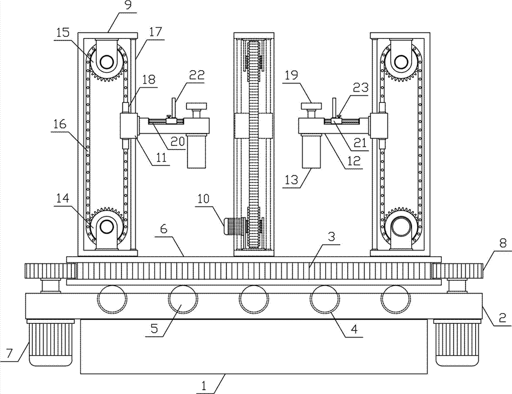
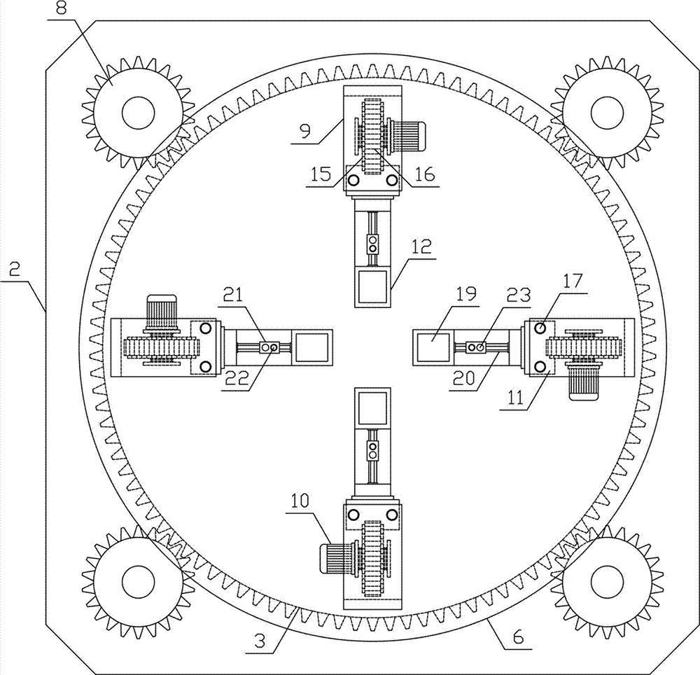
[0012] Such as figure 1 , figure 2 As shown, a bottom cover lifting and rotating installation mechanism of the present invention includes a fixed base 1, a driving base 2, a rotating gear circular plate 3 and a lifting installation mechanism. The driving base 2 is horizontally arranged on the upper side of the fixed base 1, and the upper side of the driving base 2 A plurality of spherical card slots 4 are evenly arranged, and the bearing plate universal ball 5 is rotated in the spherical card slot 4, and the rotating gear circular plate 3 is horizontally arranged on the upper side of the bearing plate universal ball 5 of ...


PUM


Abstract

The invention discloses a bottom cover lifting and rotating installation mechanism, which belongs to the field of installation auxiliary mechanical equipment. The invention includes a fixed base, a driving base, a rotating gear disc and a lifting installation mechanism. The driving base is horizontally arranged on the upper side of the fixed base, the rotating gear disc is horizontally arranged on the upper side of the universal ball of the bearing plate of the driving base, and the output end of the rotating motor The driving gear is installed horizontally, and there are several groups of lifting installation mechanisms installed vertically and symmetrically on the outer side above the circular plate of the rotating gear. The main sprocket and the auxiliary sprocket are meshed and connected by a transmission chain, and the guide plate slides vertically on the lifting guide rod. , the lifting plate is horizontally arranged on one side of the guide plate, and the output end of the installation cylinder is horizontally arranged with an installation pressing plate. The invention has a reasonable structural design, can quickly and efficiently lift and install bottom covers of various sizes and specifications stably and accurately, improves the efficiency and quality of bottom cover installation, and meets the needs of installation and use.

Description

technical field [0001] The invention belongs to the field of installation auxiliary mechanical equipment, in particular to a lifting and rotating installation mechanism for a bottom cover. Background technique [0002] The bottom cover is mainly used in container equipment. Fixing the bottom cover on the lower end of the container equipment can seal the lower end of the container to ensure that the container equipment is sealed and leak-free when storing materials. Therefore, the quality of the bottom cover installation determines the airtight performance of the container. , The bottom cover and the container equipment are mainly locked and fixed by bolts. The sealing quality of the bottom cover and the container is directly related to the long-term safe and reliable operation of the container. In the continuous production process of containers, the efficiency and quality of the installation of the bottom cover determine the output of the container production. In the process...

Claims


Application Information

Patent Timeline
IPC IPC(8): B23P19/00B23P19/04
CPCB23P19/001B23P19/04
Inventor 裘国贤
Owner TONGXIANG TANGCHAO ADVERTISEMENT CO LTD
Why Eureka
Try Eureka