
Current contact and switching device

A current and contact technology, applied in the field of current contacts and switch devices, can solve the problems of not being able to set individually, contact discharge ablation, large friction resistance, etc., to prevent contact discharge and ablation, and suppress contact reaction force. , the effect of reducing friction

Active Publication Date: 2017-09-01
北京博瑞莱智能科技集团有限公司 +2
View PDF7 Cites 4 Cited by
  • Summary
  • Abstract
  • Description
  • Claims
  • Application Information

AI Technical Summary

Problems solved by technology

[0002] The existing conductive contact methods of switch contacts are all point contacts, and when the moving contacts and static contacts move relative to each other, the friction resistance is large, and the contacts are easy to wear, resulting in extremely unstable contact resistance
In addition, when a surge current passes through, the contact reaction force of a single contact will affect the contact point at the other end, and the force that inhibits the contact from bouncing cannot directly act on the contact point, causing the contact to bounce instantly and cause the contact head discharge ablation
In addition, the moving contacts in the existing contact structure are arranged in pairs and cannot be arranged individually

Method used


Image

  • Current contact and switching device
  • Current contact and switching device
  • Current contact and switching device

Examples


Embodiment Construction

[0028] In order to make the purpose, technical solutions and advantages of the embodiments of the present invention clearer, the technical solutions in the embodiments of the present invention will be clearly and completely described below in conjunction with the drawings in the embodiments of the present invention. Obviously, the described embodiments It is a part of embodiments of the present invention, but not all embodiments. The components of the embodiments of the invention generally described and illustrated in the figures herein may be arranged and designed in a variety of different configurations.

[0029] Accordingly, the following detailed description of the embodiments of the invention provided in the accompanying drawings is not intended to limit the scope of the claimed invention, but merely represents selected embodiments of the invention. Based on the embodiments of the present invention, all other embodiments obtained by persons of ordinary skill in the art wi...


PUM


Abstract

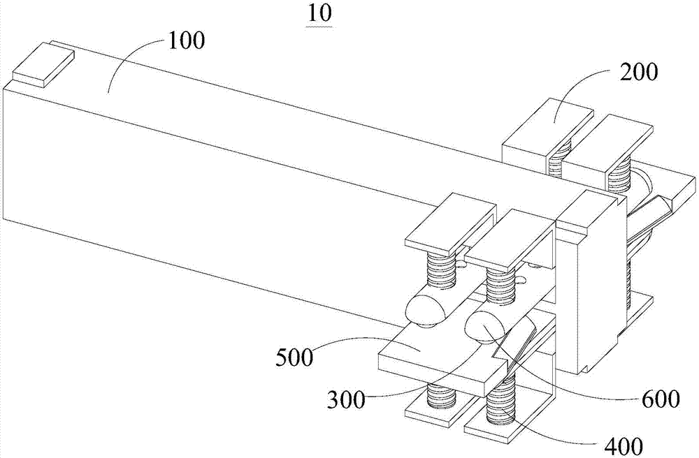
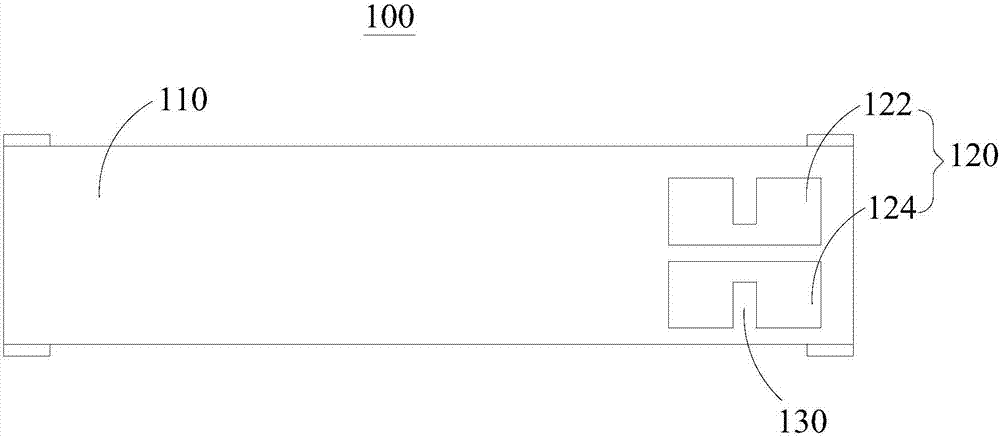
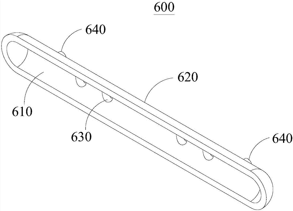
The embodiment of the invention provides a current contact and a switching device. The current contact comprises a contact carrier, supports, at least one moving contact, elastic parts and a fixed contact; the contact carrier is provided with at least one limiting mounting hole; the limiting mounting hole runs through the contact carrier. The support passes through the limiting mounting hole and is fixed on the hole side wall of the limiting mounting hole, and the supports extend out of both sides of the limiting mounting hole. At least one moving contact runs through the limiting mounting hole and extends out of both sides of the limiting mounting hole, and the elastic parts are arranged between the supports and the moving contacts, which extend out of the same sides of the limiting mounting hole. The fixed contact is in contact with at least one moving contact of the limiting mounting hole, and the moving contact can roll relative to the fixed contact. According to the current contact and the switching device which are provided by the invention, friction generated when the moving contact and the fixed contact move relatively can be effectively reduced, a counter-acting force of the contact can be effectively inhibited when an inrush current passes through the moving contact, contact discharge ablation caused by instantaneous pop-up of the contact is prevented, and the number of the moving contacts can also be freely regulated as required.

Description

technical field [0001] The invention relates to the field of current contacts, in particular to a current contact and a switch device. Background technique [0002] The existing conductive contact methods of switch contacts are all point contacts, and when the moving contacts and static contacts move relative to each other, the frictional resistance is large, and the contacts are easy to wear, resulting in extremely unstable contact resistance of the contacts. In addition, when a surge current passes through, the contact reaction force of a single contact will affect the contact point at the other end, and the force that inhibits the contact from bouncing cannot directly act on the contact point, causing the contact to bounce instantly and cause the contact Head discharge ablation. In addition, the moving contacts in the existing contact structure are arranged in pairs and cannot be arranged individually. Contents of the invention [0003] In order to overcome the above-...

Claims


Application Information

Patent Timeline
Patent Type & Authority Applications(China)
IPC IPC(8): H01H1/16H01H1/62
CPCH01H1/16H01H1/62
Inventor 魏贞祥杨福荣潘新华邢健宇张中印
Owner 北京博瑞莱智能科技集团有限公司
Learn More