
Manual coupling buffer structure

A buffer structure, manual technology, applied in railway couplings, railway car body parts, traction devices, etc., can solve the problems of high cost, large longitudinal impact, long production cycle, etc., and achieve low implementation cost and reduce longitudinal impact. , The effect of high connection reliability

Pending Publication Date: 2017-09-01
CRRC ZIYANG CO LTD
View PDF9 Cites 7 Cited by
  • Summary
  • Abstract
  • Description
  • Claims
  • Application Information

AI Technical Summary

Problems solved by technology

At present, most domestic freight locomotives use 100-type coupler buffer devices, and most EMUs use close-connected coupler buffer devices. These two coupler buffer devices have their own shortcomings for freight train units, mainly because of the longitudinal impact they receive. Larger, complex structure, and higher manufacturing process requirements, not only long production cycle, but also high cost
Especially for the narrow-gauge freight car group, because the volume of this freight car itself is small, its cargo capacity is also small, therefore, the traction force required during its operation is also relatively small, if still adopt the existing Couplers or chains used for coupling and towing between vehicles lead to higher operating costs

Method used


Image

  • Manual coupling buffer structure
  • Manual coupling buffer structure
  • Manual coupling buffer structure

Examples


Embodiment Construction

[0035] In order to make the object, technical solution and advantages of the present invention clearer, the present invention will be described in detail below in conjunction with the accompanying drawings and specific embodiments. It should be understood that the specific embodiments described here are only used to explain the present invention, not to limit the present invention.

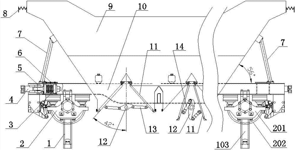
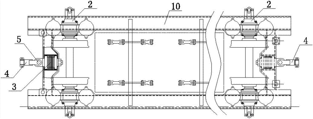
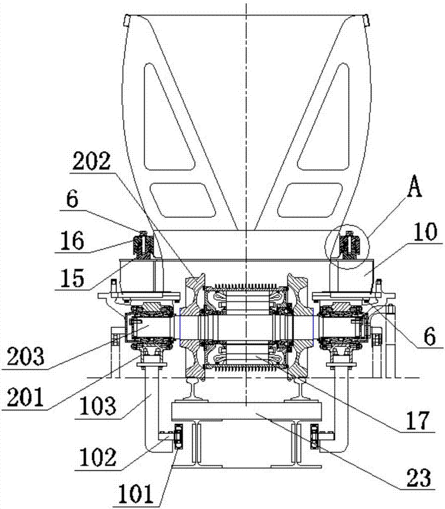
[0036] like figure 1 , figure 2 , image 3 The vehicle shown specifically includes an anti-derailment device 1, a running device 2, a carriage 9 and a frame 10. The carriage 9 is funnel-shaped and made of stainless steel, and criss-cross bending grooves are arranged on the outside of the carriage 9 Steel, the bent channel steel forms a mesh structure, and is welded together with the car body, effectively increasing the rigidity of the car body 9 . Corrugated boards 8 are respectively fixedly connected to the outer sides of the opposite ends of the entrance of the carriage 9. When several carri...


PUM


Abstract

The invention provides a manual coupling buffer structure. The manual coupling buffer structure comprises buffers (3), two clamp rings (21) and two traction rods (40). Notch grooves are formed in the clamp rings (21), and connecting necks (42) are formed in one ends of the traction rods (40); and the clamp rings (21) are mutually connected with the connecting necks (42) on the inter-adjacent traction rods (40) in a clamped mode through flange parts located on the two sides of the notch grooves, every two clamp rings (21) are connected in series through connecting bolts (6) and fixedly connected with the traction rods (40) to form a whole body, and the buffers (3) are connected at the free ends of the traction rods (40). By utilizing the manual coupling buffer structure, the longitudinal impact between vehicles can be alleviated, when the mutual coupling state between the vehicles needs to be removed, an operating worker only needs to disassemble the connecting bolts with the help of a simple auxiliary tool, and then disconnection between every two adjacent vehicles can be achieved; and the manual coupling buffer structure has the outstanding advantages that the structure is simple, operation is convenient, the coupling reliability is high and the implementation cost is low.

Description

technical field [0001] The invention relates to the technical field of vehicle coupling, in particular to a manual coupling buffer structure. Background technique [0002] The domestic passenger sports car technology is relatively mature and has reached the international leading level. However, the freight car group has just started, and many technologies are still being researched and explored, for example, the coupler buffer device and so on. At present, most domestic freight locomotives use 100-type coupler buffer devices, and most EMUs use close-connected coupler buffer devices. These two coupler buffer devices have their own shortcomings for freight train units, mainly because of the longitudinal impact they receive. Larger, complex structure, and higher manufacturing process requirements, not only long production cycle, but also high cost. Especially for the narrow-gauge freight car group, because the volume of this freight car itself is small, its cargo capacity is a...

Claims


Application Information

Patent Timeline
Patent Type & Authority Applications(China)
IPC IPC(8): B61G9/04B61G1/40
CPCB61G1/40B61G9/04
Inventor 马瑞卿陈传彬陈强黎焕先彭长福隆孝军江太宏刘凤刚
Owner CRRC ZIYANG CO LTD
Learn More