Tee pipe injection mold and using method thereof

A technology for injection molds and tee pipes, applied in the field of tee pipe injection molds, to achieve stable work, improve reliability and mold injection production efficiency, and reduce production costs

Inactive Publication Date: 2017-09-01
贵阳合众精密机械制造有限公司
View PDF3 Cites 4 Cited by
  • Summary
  • Abstract
  • Description
  • Claims
  • Application Information

AI Technical Summary

Problems solved by technology

[0003] like figure 1 As shown, when the three-way pipe product is molded, the difficulty of demoulding the product lies in the core-pulling demoulding of the 90° elbow part in the middle part. It is difficult for the mechanism to achieve multiple holes in one mold. Therefore, it is necessary to design a special core-pulling and demoulding mechanism for the elbow part to complete the demoulding of the elbow part and the corresponding mold structure for products with more than two cavities; at the same time, it is also necessary to ensure that the core-pulling mechanism is more accurate. The simpler the mold, the easier it is to process, and the principle of relatively reducing the production cost of the mold, and the simpler the mechanism, the better its reliability and stability

Method used


Image

  • Tee pipe injection mold and using method thereof
  • Tee pipe injection mold and using method thereof
  • Tee pipe injection mold and using method thereof

Examples


Embodiment Construction

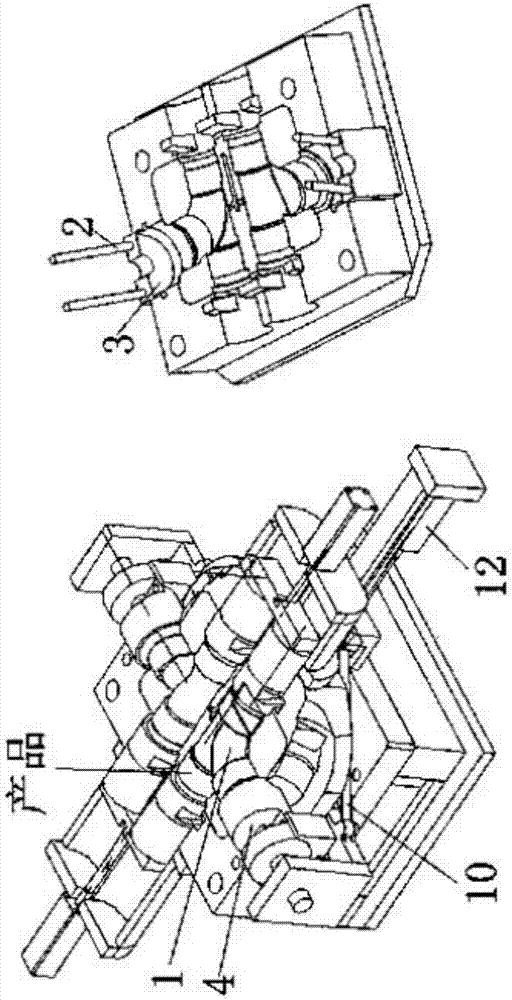
[0024] Figure 2-12 Shown is a related explanatory diagram of the present invention; a three-way pipe injection mold, including a mold base structure and a mold core-pulling part, a first elbow slider head 1, a first round pipe slider inclined guide column 2, a first Round tube slider wedge block 3, first round tube slider 4, first elbow slider head tie rod 5, left baffle 6, first round tube slider seat guide chute 7, first slot bottom plate 8, The first round tube slider seat 9, the left universal pull rod 1, the left universal seat 11, the first power cylinder 12, the first power cylinder mounting plate 13, the universal seat guide chute 14, the universal seat 15, the right universal seat Toward seat 16, right universal pull rod 17, second groove bottom plate 18, second round tube slider seat 19, second round tube slider seat guide chute 2, right baffle 21, second elbow slider head pull rod 22. The second round tube slider inclined guide column 23, the second round tube sli...


PUM


Abstract

The invention provides a tee pipe injection mold and a using method thereof. The tee pipe injection mold comprises a mold frame structure, a first position core loosing and demolding mechanism for a mold core loosing and demolding part, a second core loosing and demolding mechanism for a mold core loosing and demolding part, a third core loosing and demolding mechanism for a mold core loosing and demolding part and a fourth core loosing and demolding for a mold core loosing and demolding part, wherein the first position core loosing and demolding mechanism and the second position core loosing and demolding mechanism are a dual-linkage mechanism driven by the same oil cylinder; and the third position core loosing and demolding mechanism and the fourth position core loosing and demolding mechanism are circular pipe circular sliding block type core loosing and demolding mechanisms. Through the adoption of the technical scheme of the tee pipe injection mold provided by the invention, the complexity of a core loosing mechanism of a middle bent pipe location when a conventional multi-cavity tee pipe product is designed by a multi-cavity mold is simplified, and the mold structure of the tee pipe injection mold is simplified, so that the reliability of an arc core loosing mechanism and the production efficiency of the mold injection are improved; the production and manufacturing cost of the mold is reduced; and the tee pipe injection mold is reasonable in structural design, compact in structure, stable to operate, and safe and reliable.

Description

[0001] This application is a divisional application for an invention patent application with the application number: 2015104032275, the name of the invention-creation: a three-way pipe injection mold, and the application date: July 10, 2015. technical field [0002] The invention relates to the field of injection mold mechanism design, in particular to a three-way pipe injection mold and a method for using the same. Background technique [0003] like figure 1 As shown in the figure, when the three-way pipe product is molded, the difficulty in demoulding the product lies in the core-pulling and demoulding of the 90° elbow in the middle part. It is difficult for the mechanism to achieve multiple cavities in one mold. Therefore, it is necessary to design a special core-pulling and demolding mechanism for the elbow part to complete the demoulding of the elbow part of the product with more than two cavities and the corresponding mold structure; at the same time, it is also necess...

Claims


Application Information

Patent Timeline
Patent Type & Authority Applications(China)
IPC IPC(8): B29C45/26B29C45/33B29C45/32
CPCB29C45/2602B29C45/261B29C45/32B29C45/33B29C45/332
Inventor 不公告发明人
Owner 贵阳合众精密机械制造有限公司
Why Eureka
Try Eureka