Electronic control device
A technology for electronic control devices and electronic components, which is applied in the directions of coupling devices, transmission device control, and components of connecting devices, etc., can solve problems such as the increase of vibration influence, and achieve the effect of reducing vibration and external force, and being easy to assemble.
- Summary
- Abstract
- Description
- Claims
- Application Information
AI Technical Summary
Problems solved by technology
Method used
Image
Examples
no. 1 approach
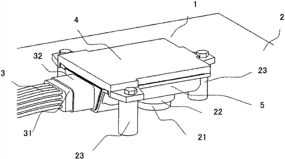
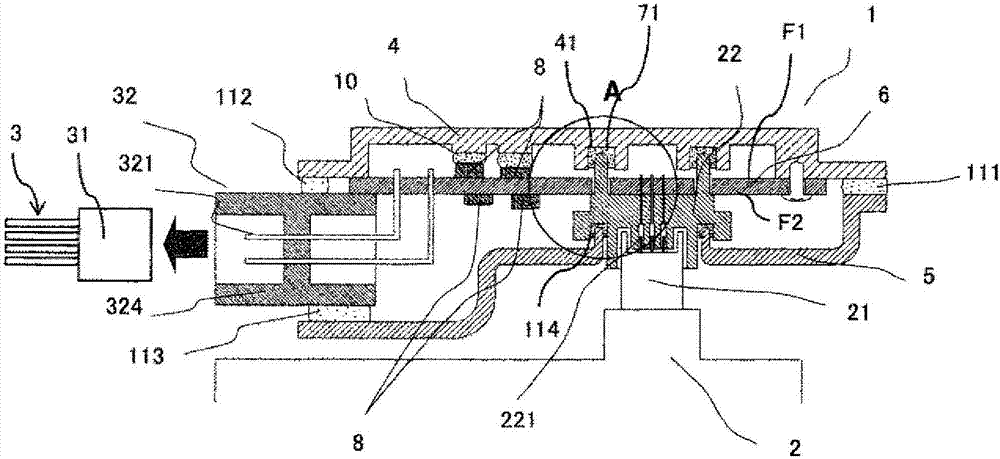
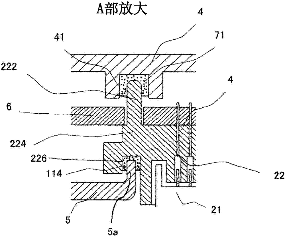
[0034] First, use Figure 1 ~ Figure 3 The configuration of the electronic control device 1 will be described. figure 1 It is a perspective view of the electronic control device 1 according to the first embodiment of the present invention. figure 2 Yes figure 1 A cross-sectional view of the electronic control unit 1 is shown. image 3 Yes figure 2 An enlarged sectional view of a main part (part A) of the electronic control unit 1 shown.
[0035] In this embodiment, in particular, an ATCU (Automatic Transmission Control Unit) as an electronic control unit installed in an engine room will be described.
[0036] like figure 2 As shown, the electronic control device 1 includes: a substrate 6 on which a first connector 22 connected to the vehicle transmission 2, a second connector 32 connected to the connector 31 of the vehicle wiring harness 3, and a plurality of electronic components 8 are installed; The base 4 and the cover 5 on which the first and second connectors 22 ...
no. 2 approach
[0063] Figure 4 It is an enlarged cross-sectional view of a main part (part A) of the electronic control device 1 according to the second embodiment of the present invention.
[0064] In this embodiment, a metal terminal 223 (a metal pin (column portion)) is provided on the first connector 22 instead of image 3 The resin pin 222 shown in. The metal terminal 223 is inserted into the concave portion 41 filled with the damping member 71 .
[0065] In this structure, the metal pin 223 is engaged with one side of the base 4, so a ratio of image 3 The resin pins 222 shown in are more securely fixed. In addition, even if the pin diameter is smaller than that of the resin pin 222, the same effect can be obtained, so the mounting area can also be reduced in size.
[0066] As described above, according to the present embodiment, assembly is easy, and the influence of vibration and external force applied from the connector can be reduced.
no. 3 approach
[0068] Figure 5 It is an enlarged cross-sectional view of a main part (part A) of the electronic control device 1 according to the third embodiment of the present invention.
[0069] In this embodiment, a screw 225 (column part) is used instead of image 3 The resin pin 222 shown in. Screws 225 are used to fix the first connecting member 22 on the base plate 6 .
[0070] The heads of the screws 225 protruding toward the back surface of the base plate 6 are engaged with the damping members 71 in the recesses 41 provided in the base 4 . Thereby, the same effect can be acquired.
[0071] In this structure, since it can be fixed at a position closer to the substrate 6, the vibration damping effect is also increased. In addition, the heads of the screws 225 are located on the surface F1 of the substrate 6 .
[0072] In addition, the screws 225 used in this structure are self-tapping screws, and are directly screwed to the first connector housing 224 made of resin. Accordingl...
PUM
 Abstract
Description
Claims
Application Information
 - R&D
- Intellectual Property
- Life Sciences
- Materials
- Tech Scout
- Unparalleled Data Quality
- Higher Quality Content
- 60% Fewer Hallucinations
Browse by: Latest US Patents, China's latest patents, Technical Efficacy Thesaurus, Application Domain, Technology Topic, Popular Technical Reports.
© 2025 PatSnap. All rights reserved.Legal|Privacy policy|Modern Slavery Act Transparency Statement|Sitemap|About US| Contact US: help@patsnap.com


