
Tiny fault location method based on input field error locating

A fault location and error location technology, applied in error detection/correction, instrumentation, electrical digital data processing, etc., can solve the problems of high positioning cost and low positioning accuracy, improve work efficiency, reduce call time, and reduce redundancy sexual effect

Active Publication Date: 2017-08-29
NANJING UNIV OF POSTS & TELECOMM
View PDF4 Cites 4 Cited by
  • Summary
  • Abstract
  • Description
  • Claims
  • Application Information

AI Technical Summary

Problems solved by technology

However, there are still many problems in these methods, such as low positioning accuracy and high positioning cost, which need further in-depth research

Method used


Image

  • Tiny fault location method based on input field error locating
  • Tiny fault location method based on input field error locating
  • Tiny fault location method based on input field error locating

Examples


Embodiment 1

[0039] Embodiment 1: realize that the concrete of the inventive method comprises the following steps:

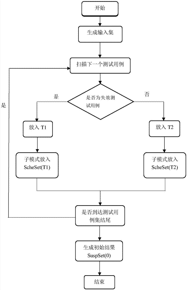
[0040] Step 1: Generate the input set, and pass such as figure 1 The failed test cases and the passed test cases in the categories shown, the specific technical solutions are as follows:

[0041] Step 1-1: Generate a τ-dimensional combined coverage table as the test case set T of the software under test SUT through existing tools;

[0042] Step 1-2: Test the SUT containing T, and judge whether the test case in T is a failure test case;

[0043] Step 1-2-1: If the judgment is yes, put the failure test case into T1;

[0044] Step 1-2-2: If the judgment is no, put the passed test case into T2;

[0045] Steps 1-3: generate sub-patterns;

[0046] Step 1-3-1: Put all sub-schemas of T1 into ScheSet(T1);

[0047] Step 1-3-2: Put all sub-schemas of T2 into ScheSet(T2);

[0048] Step 1-4: Generate initial result SuspSet(0)=ScheSet(T1)-ScheSet(T2);

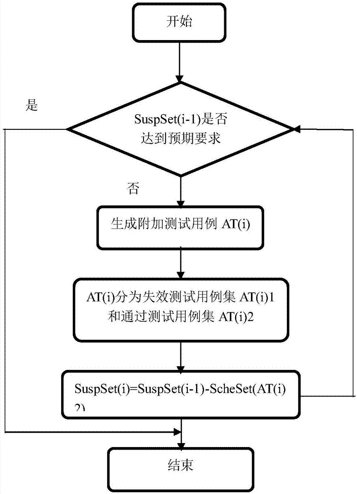
[0049] Step 2: Obtain the fa...

Embodiment 2

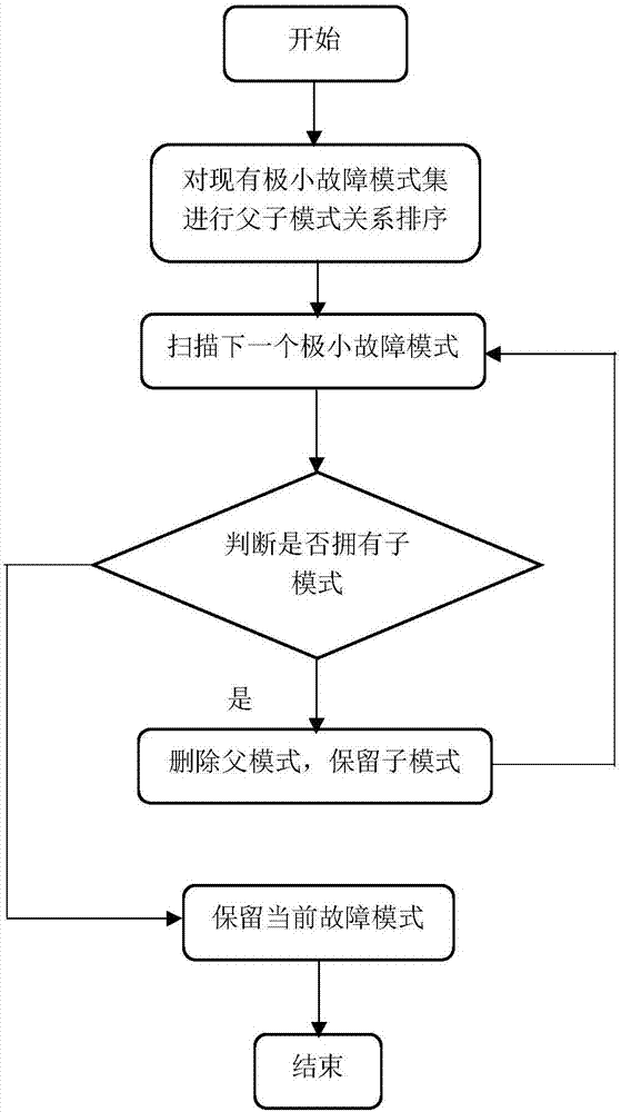
[0061] Specific application scenarios: the present invention considers that when there are a large number of test cases in the test case set, the fault location results obtained by the iterative interactive fault location method will have a certain degree of redundancy, and the more the number of test cases, the greater the severity of the redundancy. The higher the value is, the obtained minimal fault mode set is too large, making the efficiency of minimal fault location not high enough. In this case, the present invention improves and optimizes on the basis of the iterative interactive fault location method, and improves the efficiency of very small fault location. Firstly, the input set is generated and analyzed, and the failure test case set and the pass test case set are classified, and then the fault localization result obtained by the iterative interactive fault localization method is an unreduced minimal fault mode set, and then the minimal fault mode set is used The p...


PUM


Abstract

The invention discloses a tiny fault location method based on input field error locating. The method comprises the following specific steps that firstly, an input set is generated, analyzed and classified so as to form ineffective test cases and approved test cases; then, a fault location result is obtained through an interactive iteration fault location method, and a tiny fault mode set which is not subjected to reduction is obtained; finally, the obtained tiny fault modes which are not subjected to reduction are subjected to reduction so as to reduce the redundancy, and a simpler tiny fault mode set is obtained. According to the tiny fault location method, optimization is further conducted based on the existing interactive iteration fault location method, the tiny fault modes are subjected to reduction, the redundancy of the tiny fault modes is reduced, and it is ensured that tiny fault location achieves a better effect. The method can assist of reducing the call time of program developers needing to use the tiny fault mode set, and the working efficiency of the program developers is effectively imrproved.

Description

technical field [0001] The invention belongs to the field of software testing, and relates to a fault location in combined testing, in particular to improving the location method in the environment where the existing method contains many implicit assumptions and the error location capability of the existing method is limited. Background technique [0002] Software testing is an essential process in software engineering to identify the correctness, integrity, security and quality of software, and is an important link to ensure software quality. The key issue of software testing is to find the smallest possible set of test cases and find potential problems in the software to be tested at the lowest cost. According to different stages of software development, different test objects, a series of software testing methods have been proposed based on different theories and perspectives. In different stages of software development, testing is also divided into unit testing, integra...

Claims


Application Information

Patent Timeline
Patent Type & Authority Applications(China)
IPC IPC(8): G06F11/36
CPCG06F11/3684G06F11/3688G06F11/3692
Inventor 王子元季芊
Owner NANJING UNIV OF POSTS & TELECOMM
Learn More