Fast assembly type ceiling lamp

A chandelier, fast technology, applied in the direction of lighting devices, fixed lighting devices, components of lighting devices, etc., can solve the problems of strengthening the position of solder joints, potential safety hazards of weak welding, and complicated chandelier assembly, etc., to achieve high position Effect

Active Publication Date: 2017-08-29
ZHEJIANG KAIYAO LIGHTING
View PDF4 Cites 0 Cited by
  • Summary
  • Abstract
  • Description
  • Claims
  • Application Information

AI Technical Summary

Problems solved by technology

However, this welding method has potential safety hazards of poor welding, and all the weight of the light frame needs to be carried by the solder joints of the light frame and the suspender, which further enhances the stress on the solder joints, and the solder joints are prone to fall off, resulting in light stand dropped
The existing chandelier of this type is complicated to assemble, the assembly time is long, and the installation efficiency is low

Method used


Image

  • Fast assembly type ceiling lamp
  • Fast assembly type ceiling lamp
  • Fast assembly type ceiling lamp

Examples


Embodiment 1

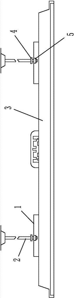
[0021] Embodiment 1: as figure 1 As shown, a quick-install pendant lamp includes a lamp body 3 and a suspender 2. Several lamp stands 1 are arranged on the upper surface of the lamp body. slot, the axis of the boom is provided with a positioning hole, the bottom of the boom is provided with an upper limit nut 4, the boom is detachably connected to the light stand through a limit connector, the limit connector includes a connecting column, and one end of the connecting column is provided with a The diameter of the limit plate is larger than that of the connecting column. The bottom of the limit plate is provided with a lower limit nut 5. The lower limit nut is fixedly connected with the limit plate. The connecting column and the limit plate are connected in one piece. The connection is in the positioning hole of the suspender and is threadedly connected with the suspender, and the diameter of the connecting column matches the width of the fixing groove.

[0022] A lamp holder ...

Embodiment 2

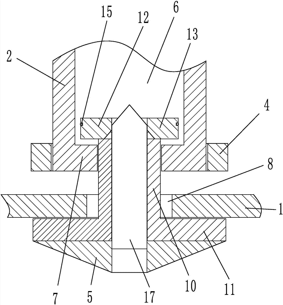
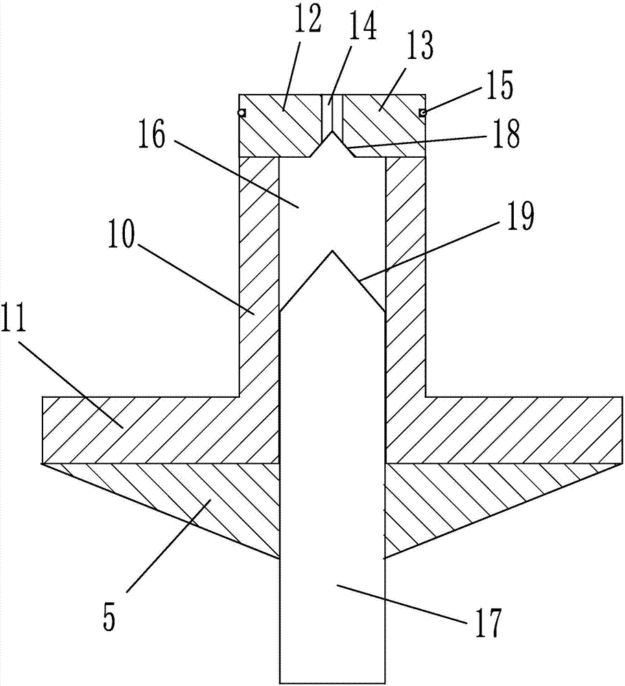
[0023] Embodiment 2: The structure of this embodiment is basically the same as that of Embodiment 1, the difference is that, as figure 2 , 3 , 4, 5, the bottom of the boom extends to the axial direction with a positioning ring 7, the inner diameter of the positioning ring is smaller than the diameter of the positioning hole; the end of the connecting column 10 away from the limit plate is provided with a ring-shaped turning block, the turning block A fixed groove around the axis of the rotary block is provided on the outer wall of the rotary block, and a tightening ring 15 sleeved on the outside of the rotary block is arranged in the fixed groove. A guide hole 14 is provided at the axis of the rotary block. The rotary block includes a left rotary block 12 and a right rotary block. Block 13, the bottom of left turn block and right turn block are all provided with bump 20, and the end face of connecting column is provided with the chute 21 that matches with bump, and chute is d...

Embodiment 3

[0025] Embodiment 3: The structure of this embodiment is basically the same as that of Embodiment 2, the difference is that, as Figure 8 As shown, a guide groove 24 is provided at the axis of the sliding chamber, and the guide groove is parallel to the axis direction of the connecting column. A vibrating spring 25 is arranged in the guide groove. The axis of the vibrating spring is parallel to the axis of the connecting column and supports the ball. When the ball is subjected to When the pressure of the left turn block and the right turn block is applied, the vibration spring can push the ball to exert an external force on the bump, and use the external force to resist gravity, avoiding excessive extrusion of the ball by the bump, and further reducing the connection between the left turn block and the right turn block and the connecting column Swipe between. At the same time, when the adjusting column squeezes into the guide hole, the direction of the extrusion force on the l...


PUM


Abstract

The invention relates to a lamp, in particular to a fast assembly type ceiling lamp. The fast assembly type ceiling lamp comprises a lamp body and suspenders. A plurality of lamp supports are arranged on the upper end face of the lamp body. The cross section of each lamp support is of an n shape. Each lamp support is provided with a fixing groove with one end open. A locating hole is formed in the axis portion of each suspender. An upper limiting nut is arranged on the bottom of each suspender. The suspenders are detachably connected with the lamp supports through limiting connecting parts. Each limiting connecting part comprises a connecting column. One end of each connecting column is provided with a limiting disc with the diameter larger than that of the connecting column. A lower limiting nut is arranged on the bottom of each limiting disc. Each connecting column and the corresponding limiting disc are integrally connected. Each connecting column penetrates through the corresponding lamp support from bottom to top, is detachably connected to the interior of the locating hole of the corresponding suspender and is in threaded connection with the suspender, and the diameter of each connecting column is matched with the width of the corresponding fixing groove. The ceiling lamp has the beneficial effects that the suspenders and the lamp supports can be connected effectively, the connecting strength is enhanced, the welding position is prevented from bearing external force, potential risk is reduced, and assembling efficiency is improved.

Description

technical field [0001] The invention relates to a lamp, in particular to a fast-installation pendant lamp. Background technique [0002] In the existing chandelier, the suspender and the base on the lamp stand are welded and fixed, so as to realize the fixing of the lamp stand and the suspender in this way. However, this welding method has potential safety hazards of poor welding, and all the weight of the light frame needs to be carried by the solder joints of the light frame and the suspender, which further enhances the stress on the solder joints, and the solder joints are prone to fall off, resulting in Light stand fell. The existing pendant lights of this type are complicated to assemble, the assembly man-hours are long, and the installation efficiency is low. Contents of the invention [0003] The present invention mainly aims at the above-mentioned problems, and provides a quick-mounted chandelier that can effectively realize the connection between the suspender a...

Claims


Application Information

Patent Timeline
Patent Type & Authority Applications(China)
IPC IPC(8): F21S8/06F21V17/12
CPCF21S8/063F21V17/12
Inventor 郭启恒王华建
Owner ZHEJIANG KAIYAO LIGHTING
Why Eureka
Try Eureka