Running safety control device of vehicle
A driving safety and control device technology, applied to vehicle components, wheels, brakes, etc., can solve problems such as easily damaged road surfaces, complicated operations, shortened tire service life, etc., and achieve the effects of prolonging service life, facilitating back and forth movement, and reducing friction
- Summary
- Abstract
- Description
- Claims
- Application Information
AI Technical Summary
Problems solved by technology
Method used
Image

Examples
Embodiment 1
[0041] Embodiment 1 (Slope Parking)
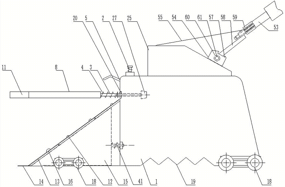
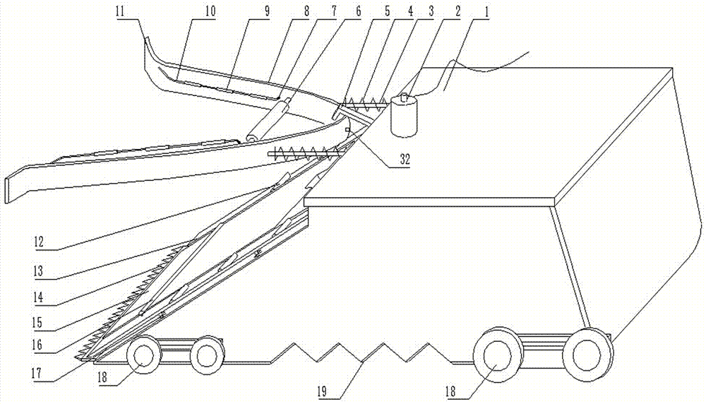
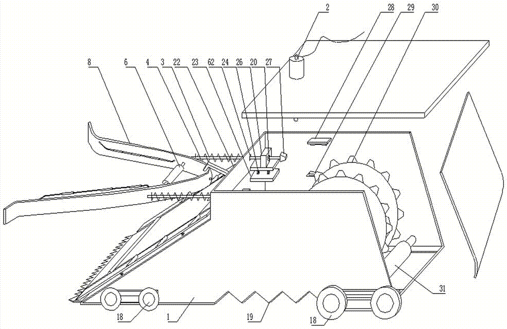
[0042] 1. The power reversing switch 63 controls the electric push rod 53 to extend forward, and the trapezoidal bracket 1 approaches the angle between the wheel a and the road surface under the guidance of the roller 18;
[0043] 2. The trapezoidal bracket 1 continues to move forward, and the curved bracket 8 embraces both sides of the wheel a under the guidance of the abduction edge 11;
[0044] 3. The trapezoidal bracket 1 continues to move forward, the one-way roller 6 and the wheel a lightly touch the arc bracket 8 and then move in translation, the second contact 32 first touches the second contact 34, and the first indicator light c prompts the wheel a is in contact with the one-way roller 6;
[0045] 4. The electric push rod 53 continues to extend forward, and the arc-shaped bracket 8 continues to move backward until the wheel a is fully pressed against the wedge-shaped seat 15, the side roller 12 is pressed down, and the roller 18...
Embodiment 2
[0046] Example 2 (normal start on a ramp)
[0047] 1. Start the vehicle on the basis of Embodiment 1, and the forward wheel a moves the arc-shaped bracket 8 upward;
[0048] 2. The first contact 27 touches the lower switch 29, and the electric push rod 53 drives the trapezoidal bracket 1 to retract in a short stroke;
[0049] 3. The trapezoidal bracket 1 moves back to the wheel a and lightly touches the one-way roller 6. The arc bracket 8 is reset to a horizontal state under the action of the fourth compression spring 24 and the first compression spring 4. At the same time, the first contact 27 Disconnect with the lower switch 29, and the electric push rod 53 stops the retraction action;
[0050] 4. After the pressure of the wheel a is released, the wheel a lightly touches the one-way roller 6, the side roller 12, and the roller 9; the side roller 12 returns to the normal state under the action of the third compression spring 17 and the roller 18 under the action of the sixth...
Embodiment 3
[0052] Embodiment 3 (stop walking after starting on the ramp)
[0053] 1. On the basis of Embodiment 2, the vehicle walks backwards, and the wheel a pushes back through the one-way roller 6 and presses down on the arc-shaped bracket 8;
[0054] 2. The first contact 27 touches the upper switch 28 to control the electric push rod 53 to extend forward;
[0055] 3. The wedge seat 15 is inserted into the angle between the wheel a and the ground to prevent the vehicle from walking backward;
[0056] 4. After the vehicle moves, the pressure on the arc bracket 8 is released from the wheel a, and the wheel a touches the one-way roller 6, the side roller 12 and the roller 9 lightly;
[0057] 5. Driven by the fourth compression spring 24 and the first compression spring 4, the arc-shaped bracket 8 is reset to be horizontal.
PUM
 Abstract
Description
Claims
Application Information
 - R&D
- Intellectual Property
- Life Sciences
- Materials
- Tech Scout
- Unparalleled Data Quality
- Higher Quality Content
- 60% Fewer Hallucinations
Browse by: Latest US Patents, China's latest patents, Technical Efficacy Thesaurus, Application Domain, Technology Topic, Popular Technical Reports.
© 2025 PatSnap. All rights reserved.Legal|Privacy policy|Modern Slavery Act Transparency Statement|Sitemap|About US| Contact US: help@patsnap.com