
Novel electric system reactive power compensation system

A power system and power compensation technology, applied in the power field, can solve problems such as voltage fluctuations at the back-end electrical equipment, achieve real-time monitoring, improve the quality of power supply voltage, and achieve automatic real-time compensation.

Inactive Publication Date: 2017-08-22
合肥市闵葵电力工程有限公司
View PDF2 Cites 7 Cited by
  • Summary
  • Abstract
  • Description
  • Claims
  • Application Information

AI Technical Summary

Problems solved by technology

[0003] At present, mainstream reactive power compensation controllers use current and voltage sampling methods to analyze the phase difference of current and voltage. After logic operations and setting switching strategies, capacitors are put into groups. The current sampling is mainly taken from a certain phase, and the voltage sampling is collected. Two-phase, currently there are more and more single-phase devices that introduce inductive lag reactive power, and most of them are distributed in A / B / C three-phase. The current single-phase sampling data can only reflect the current-voltage phase relationship of a certain phase. According to this Putting in a three-phase capacitor will cause undercompensation or overcompensation to the other two phases. Undercompensation or overcompensation will cause voltage fluctuations at the back-end electrical equipment.

Method used


Image

  • Novel electric system reactive power compensation system

Examples


Embodiment Construction

[0019] In order to facilitate the understanding of the present invention, the present invention will be described more fully below with reference to the associated drawings. Several embodiments of the invention are shown in the drawings. However, the present invention can be implemented in many different forms and is not limited to various forms. Unless otherwise defined, all technical and scientific terms used herein have the same meaning as commonly understood by one skilled in the technical field of the present invention.

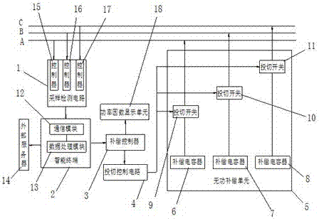
[0020] Such as figure 1 As shown, a new type of reactive power compensation system for power systems includes a sampling detection circuit 1, an intelligent terminal 2, a compensation controller 3, a switching control circuit 4 and a reactive power compensation unit 5, wherein the input terminal of the sampling detection circuit 1 is connected to For a three-phase power grid, the output end of the sampling detection circuit 1 is connected to the compari...


PUM


Abstract

The invention discloses a novel electric system reactive power compensation system. The novel electric system reactive power compensation system comprises a sampling detection circuit, an intelligent terminal, a compensation controller, a switching control circuit and a reactive compensation unit. The input end of the sampling detection circuit is connected with a three-phase power grid. The output end of the sampling detection circuit is connected with an intelligent terminal. The intelligent terminal is connected with the compensation controller. The compensation controller is connected with the switching control circuit. The switching control circuit is connected with the reactive compensation unit. According to current sampling detection in a sampling detection circuit power grid, the switching control circuit is controlled according to a detection result, a capacitor is switched on or switched off according to certain rules, reactive compensation is performed on the three-phase power grid, automatic real-time compensation for reactive power is achieved, the power supply voltage quality is improved, and the problem that due to the fact that other two-phase under-compensation or over-compensation is caused by existing current single-phase sampling detection, voltage fluctuations of rear-end electric consumption are caused is solved.

Description

technical field [0001] The invention relates to the technical field of electric power, in particular to a novel power system reactive power compensation system. Background technique [0002] The significance of power consumption management is to be able to provide stable power quality to power consumption clients. Voltage is one of the important indicators of power quality. Both the unit consumption of electricity and the electricity consumption of people's lives have a direct impact. Reactive power is an important factor affecting voltage quality, voltage quality and reactive power are inseparable, voltage problem is essentially a reactive power problem. It is of great significance to solve the problem of reactive power compensation. According to the principle of reactive power balance and the principle of reactive power compensation, the influence of reactive power compensation technology on the power factor of low-voltage power grid is introduced. Through reactive powe...

Claims


Application Information

Patent Timeline
Patent Type & Authority Applications(China)
IPC IPC(8): H02J3/18H02J13/00
CPCH02J3/1821H02J13/00001Y02E40/30Y02E40/70Y04S10/22
Inventor 何飞
Owner 合肥市闵葵电力工程有限公司
Learn More