
One-way self-locking type mechanical hand

A self-locking, manipulator technology, applied in the field of manipulators, can solve the problems of high safety hazards and the manipulator does not have self-locking function, etc., and achieve the effect of preventing safety hazards and facilitating the reset effect.

Inactive Publication Date: 2017-08-22
CHANGZHOU COLLEGE OF INFORMATION TECH
View PDF5 Cites 7 Cited by
  • Summary
  • Abstract
  • Description
  • Claims
  • Application Information

AI Technical Summary

Problems solved by technology

[0003] The technical problem to be solved by the present invention is: to overcome the technical problem that the manipulator in the prior art does not have a good self-locking function and cause great safety hazards, the present invention provides a one-way self-locking manipulator

Method used


Image

  • One-way self-locking type mechanical hand
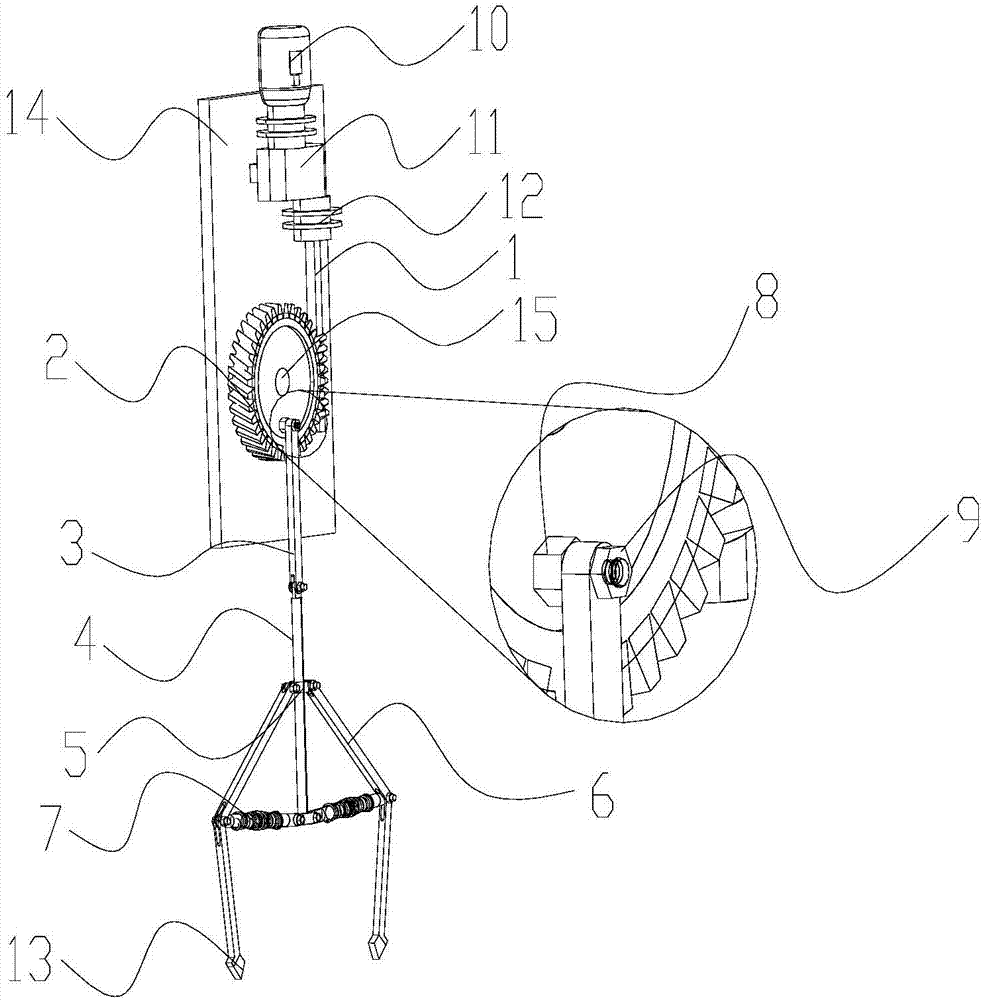
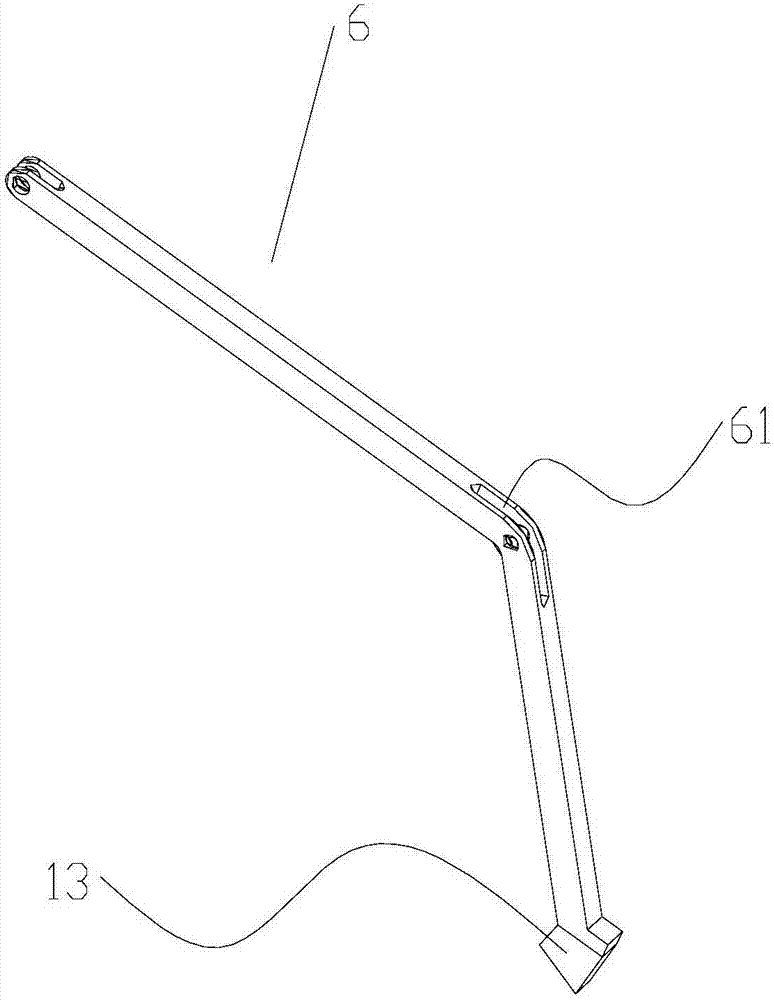
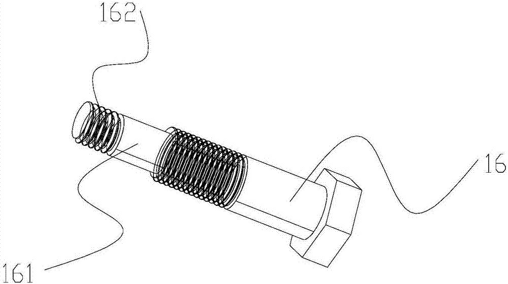
  • One-way self-locking type mechanical hand
  • One-way self-locking type mechanical hand

Examples


Embodiment Construction

[0021] The present invention is described in further detail now in conjunction with accompanying drawing. These drawings are all simplified schematic diagrams, which only illustrate the basic structure of the present invention in a schematic manner, so they only show the configurations related to the present invention.

[0022] Such as Figure 1~5 As shown, the present invention provides a one-way self-locking manipulator, including: a drive assembly, the drive assembly is used to provide power; a transmission assembly, the transmission assembly includes a worm 1, a worm wheel 2, a first connecting rod 3 and a second connecting rod 4. The worm 1 is fixedly connected and interlocked with the drive assembly, the worm gear 2 meshes with the worm 1, one end of the first connecting rod 3 is hinged on the end face of the worm gear 2, and the other end is hinged with one end of the second connecting rod 4; the clamping component, the clamping The holding assembly includes a sleeve h...


PUM


Abstract

The invention relates to a one-way self-locking type mechanical hand. The one-way self-locking type mechanical hand comprises a driving assembly used for providing power; a transmitting assembly and a clamping assembly. The transmitting assembly comprises a worm rod, a worm wheel, a first connecting rod and a second connecting rod, the worm rod is fixedly connected with the driving assembly in a linkage mode, the worm wheel meshes with the worm rod, one end of the first connecting rod is hinged to the surface of the worm wheel, and the other end of the first connecting rod is hinged to one end of the second connecting rod; the clamping assembly comprises two clamping sections and a sleeving head, the sleeving head is arranged at the second connecting rod in a sleeving mode, and the second connecting rod is capable of sliding up and down relative to the sleeving head, one ends of the two clamping sections are hinged to the sleeving head, each clamping section includes a clamping rod and an telescopic rod group, wherein one end of the clamping rod is hinged to the sleeving head, and the flexing rod group is capable of stretching and contracting. According to the single way self-locking type mechanical hand, firstly, through the arrangement of the worm wheel and the worm rod, the effects of holding and loosing are achieved, secondly, the worm wheel and the worm rod have the self-locking character, and even if the driving assembly suddenly stops working, the holding effect is not changed.

Description

technical field [0001] The invention relates to a manipulator, in particular to a one-way self-locking manipulator. Background technique [0002] Most of the manipulators in the prior art rely on continuous external force output to achieve the effect of fixed clamping. Once such a manipulator is powered off, the clamping force of the manipulator disappears because the continuous external force output is blocked. , if it is not holding something, there will be no bad effects. If it is holding something, because the gripping force of the manipulator disappears, the goods will fall or even hurt people, so it is a safety hazard great. Contents of the invention [0003] The technical problem to be solved by the present invention is: to overcome the technical problem in the prior art that the manipulator does not have a good self-locking function, resulting in a large safety hazard, and the present invention provides a one-way self-locking manipulator. [0004] The technical s...

Claims


Application Information

Patent Timeline
Patent Type & Authority Applications(China)
IPC IPC(8): B25J9/10B25J9/12
CPCB25J9/10B25J9/12
Inventor 罗彬宾罗腾腾嵇明军
Owner CHANGZHOU COLLEGE OF INFORMATION TECH
Learn More