Blade surface grinding device

A blade and support rod technology, which is applied in the directions of grinding machines, grinding workpiece supports, grinding machine parts, etc., can solve the problems of large grinding volume, low precision, and large diameter of propeller blades.

Inactive Publication Date: 2017-08-22
SUZHOU YASIKE PRECISION CNC CO LTD
View PDF10 Cites 11 Cited by
  • Summary
  • Abstract
  • Description
  • Claims
  • Application Information

AI Technical Summary

Problems solved by technology

[0002] At present, there are relatively few grinding machines for large propellers of large ships, and they mainly encounter the following problems: 1. The diameter of propeller blades is relatively large, and the grinding speed of general grinding machines cannot meet the requirements; 2. The grinding volume is large, requiring Constantly replace the grinding wheel, and the grinding of the propeller requires relatively high thickness and diameter of the grinding wheel, so as to ensure the grinding accuracy, so the general grinding machine cannot be completed; 3. The existing grinding wheel has poor stability, which is likely to cause safety hazards and property damage loss
[0007] 1. Non-automatic propeller grinding machine, each grinding action needs to be completed manually, the grinding efficiency is low, the precision is low and the labor cost is high
[0008] 2. Use mechanical equipment for grinding and polishing. The current equipment has a single function and can only polish part of the flat surface. It cannot adapt to complex curved surfaces and the accuracy is not high.

Method used


Image

  • Blade surface grinding device
  • Blade surface grinding device

Examples


Embodiment Construction

[0041] The present invention will be further described in detail below in conjunction with the accompanying drawings and specific preferred embodiments.

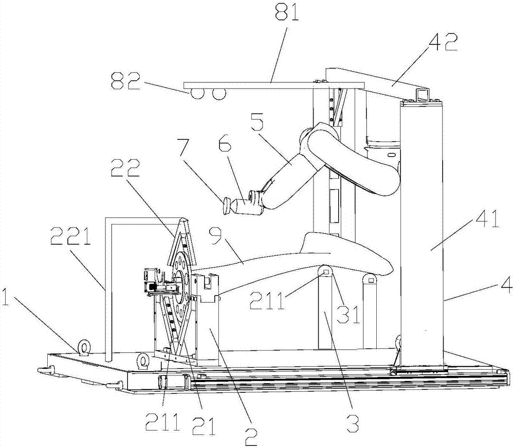
[0042] like figure 1 As shown, a paddle surface grinding device includes a base 1, a paddle chassis clamp 2, a paddle support rod 3, a gantry frame 4, a mechanical arm 5, an air bearing spindle 6, a conical grinding wheel 7, an inclination sensor 71, and a curved surface Detect components and host computer.

[0043] The paddle 9 includes a circular paddle chassis and paddle blades.

[0044] The paddle chassis clamp is fixed on the base and is used for clamping and fixing the paddle chassis.

[0045] There are two blade support rods for supporting the blades of the blade; each blade support rod is slidably arranged on the base, and the height of each blade support rod can be raised and lowered and locked.

[0046] The gantry frame includes two vertical bars and a cross bar fixed on the top of the two vertical bars, and the...


PUM


Abstract

The invention discloses a paddle surface grinding device, which comprises a base, a paddle chassis clamp, a paddle support rod, a gantry frame, a mechanical arm, an air-floating spindle, a conical grinding wheel, an inclination sensor, a curved surface detection component and a host computer. The mechanical arm is fixedly connected to the air-floating spindle; the air-floating spindle includes a mandrel and a pressure sensor; the conical grinding wheel is coaxially sleeved at the tail end of the mandrel, and the extension line of the conical generatrix of the conical grinding wheel is formed by the central axis of the conical grinding wheel. The included angle is 15°-75°; the inclination sensor is arranged on the non-grinding side of the conical grinding wheel; the curved surface detection component includes a horizontal horizontal plate and at least two laser sensors. The invention has a high degree of automation, can automatically plan the grinding path of the blade, can adapt to the complex blade curved surface, can automatically adjust the inclination angle of the conical grinding wheel, and makes the conical generatrix of the conical grinding wheel consistent with the blade curved surface, and at the same time, can The grinding force is controlled within a set range, so that the grinding precision is high.

Description

technical field [0001] The invention relates to the technical field of curved surface grinding, in particular to a paddle surface grinding device. Background technique [0002] At present, there are relatively few grinding machines for large propellers of large ships, and they mainly encounter the following problems: 1. The diameter of propeller blades is relatively large, and the grinding speed of general grinding machines cannot meet the requirements; 2. The grinding volume is large, requiring Constantly replace the grinding wheel, and the grinding of the propeller requires relatively high thickness and diameter of the grinding wheel, so as to ensure the grinding accuracy, so the general grinding machine cannot be completed; 3. The existing grinding wheel has poor stability, which is likely to cause safety hazards and property damage loss. The grinding machines currently used on large propellers generally have the disadvantages of poor pertinence, complicated and inconven...

Claims


Application Information

Patent Timeline
Patent Type & Authority Applications(China)
IPC IPC(8): B24B19/14B24B41/06B24B49/00B24B41/04
CPCB24B19/14B24B41/04B24B41/06B24B49/00
Inventor 马峻薛松
Owner SUZHOU YASIKE PRECISION CNC CO LTD
Why Eureka
Try Eureka