Screw compressor element

A technology of screw compressors and components, applied in pump components, mechanical equipment, machines/engines, etc., can solve problems such as impeding good filling of blade gaps and mixing loss in hollow parts, and achieve the effect of eliminating mixing loss and easy to achieve.

Active Publication Date: 2017-08-18
ATLAS COPCO AIRPOWER NV
View PDF10 Cites 1 Cited by
  • Summary
  • Abstract
  • Description
  • Claims
  • Application Information

AI Technical Summary

Problems solved by technology

[0027] However, these edges will prevent a good filling of the spaces between the blades, since they ensure that the hollow of the casing is at least partially or temporarily closed when the screw rotor rotates
[0028] Also, mixing losses still occur in the hollow

Method used


Image

  • Screw compressor element
  • Screw compressor element
  • Screw compressor element

Examples


Embodiment Construction

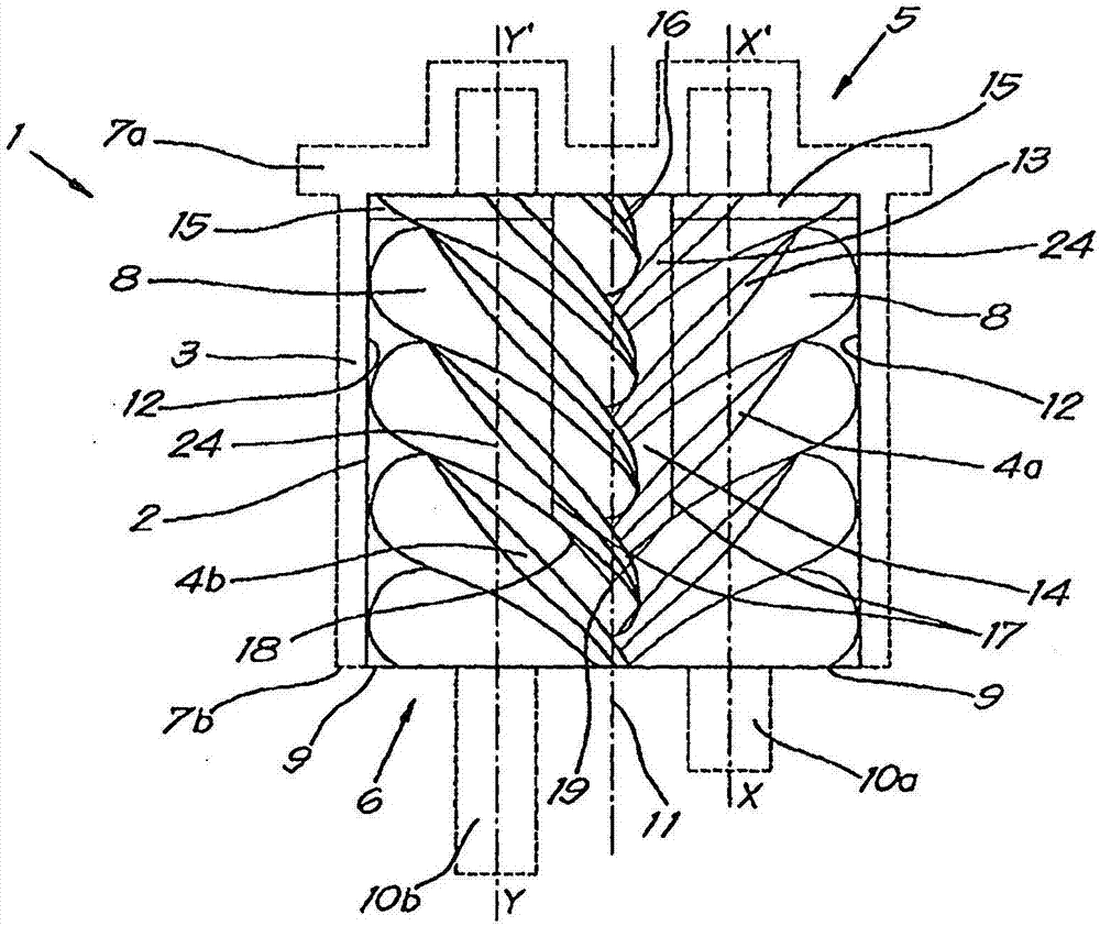
[0051] figure 1 A perspective view of the screw compressor element 1 according to the present invention is schematically shown. Two screw rotors 4a and 4b, namely, a female screw rotor 4a and a male screw rotor 4b, are fixed in at least the double cylindrical chamber 2 of the housing 3.

[0052] The screw compressor element 1 has an air inlet side 5 and an air outlet side 6. The air inlet end face 7a of the housing 3 is shown at the air inlet side 5.

[0053] For the sake of clarity, other components of the screw compressor element 1 are not shown, such as the exhaust port end face 7b on the exhaust port side 6, bearings and seals.

[0054] in figure 1 In this, it can be clearly seen that the spiral rotors 4a and 4b are provided with blades 8 which mesh with each other to rotate and are fixed in the double cylindrical chamber 2.

[0055] The chamber 2 is composed of two single cylindrical rotor chambers 9, in which the axes X-X' and Y-Y' of the rotor chamber 9 coincide with the axes 1...


PUM


Abstract

Screw compressor element with a housing (3) and two screw rotors (4a, 4b) that are affixed in the housing (3) in a double cylindrical chamber (2) provided to this end, whereby the housing (3) is provided with an inlet opening (13) on the inlet side (5) of the screw compressor element (1), whereby the inlet opening (13) extends in the cylindrical walls (12) of the double cylindrical chamber (2) with at least a section (14) that extends in an axial direction, and a transverse section (15) connecting thereto in the form of a strip that extends from the axial section (14) on the inlet side (5) to a side (17) of the section (14) in a direction transverse to the axial direction.

Description

Technical field [0001] The invention relates to screw compressor elements for compressing gas. [0002] More specifically, the present invention relates to a screw compressor element, including a casing and two spiral rotors, the two spiral rotors are rotatably fixed in the casing in a double cylindrical chamber provided for this purpose, the double cylindrical chamber is Two single-cylindrical rotor chambers are composed of two single-cylindrical rotor chambers converging with each other along two axial ribs or "sharp ridges". The double-cylindrical chamber is composed of the cylindrical wall of the rotor chamber and the two shells. The two end faces are the end face on the air inlet side of the screw compressor element and the end face on the air outlet side, wherein the shell is provided with the gas to be compressed at the air inlet side of the screw compressor element Air inlet. Background technique [0003] The air inlets ensure that gas can be supplied to the rotor chamber...

Claims


Application Information

Patent Timeline
Patent Type & Authority Applications(China)
IPC IPC(8): F04C29/12F04C18/16
CPCF04C18/16F04C29/12F04C2240/30F04C2250/101
Inventor K·R·L·罗德菲尔
Owner ATLAS COPCO AIRPOWER NV
Why Eureka
Try Eureka