
Camera component and electronic equipment

A camera component and camera technology, applied in televisions, electrical components, color TVs, etc., can solve the problems of poor depth of field ranging accuracy, poor background blur effect, large deviation of the center of view, etc., to reduce the deviation of the center of view, Improve the background blur effect and enhance the imaging effect

Inactive Publication Date: 2017-08-18
GUANGDONG OPPO MOBILE TELECOMM CORP LTD
View PDF6 Cites 5 Cited by
  • Summary
  • Abstract
  • Description
  • Claims
  • Application Information

AI Technical Summary

Problems solved by technology

[0002] In related technologies, configuring multiple cameras on electronic devices has gradually become the mainstream configuration of mobile phones. However, the distance between the two cameras on the market is too short, the deviation of the center of view angle is small, and the composite effect is better. The accuracy effect is poor, and the background blur effect is not good; the distance is too far, the depth of field ranging accuracy is high, the background blur effect is good, but the center of view angle is large, and the composite effect is biased

Method used


Image

  • Camera component and electronic equipment
  • Camera component and electronic equipment
  • Camera component and electronic equipment

Examples


Embodiment Construction

[0020] Embodiments of the present invention are described in detail below, examples of which are shown in the drawings, wherein the same or similar reference numerals designate the same or similar elements or elements having the same or similar functions throughout. The embodiments described below by referring to the figures are exemplary only for explaining the present invention and should not be construed as limiting the present invention.

[0021] In describing the present invention, it should be understood that the terms "center", "longitudinal", "transverse", "length", "width", "thickness", "front", "rear", "left", " The orientation or positional relationship indicated by "right", "vertical", "horizontal", "top", "bottom", "inner", "outer", etc. is based on the orientation or positional relationship shown in the drawings, and is only for the convenience of description The present invention and simplified description do not indicate or imply that the device or element refe...


PUM


Abstract

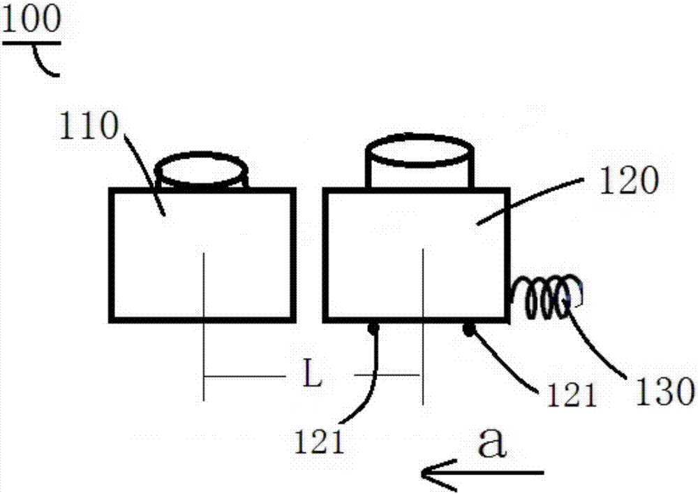
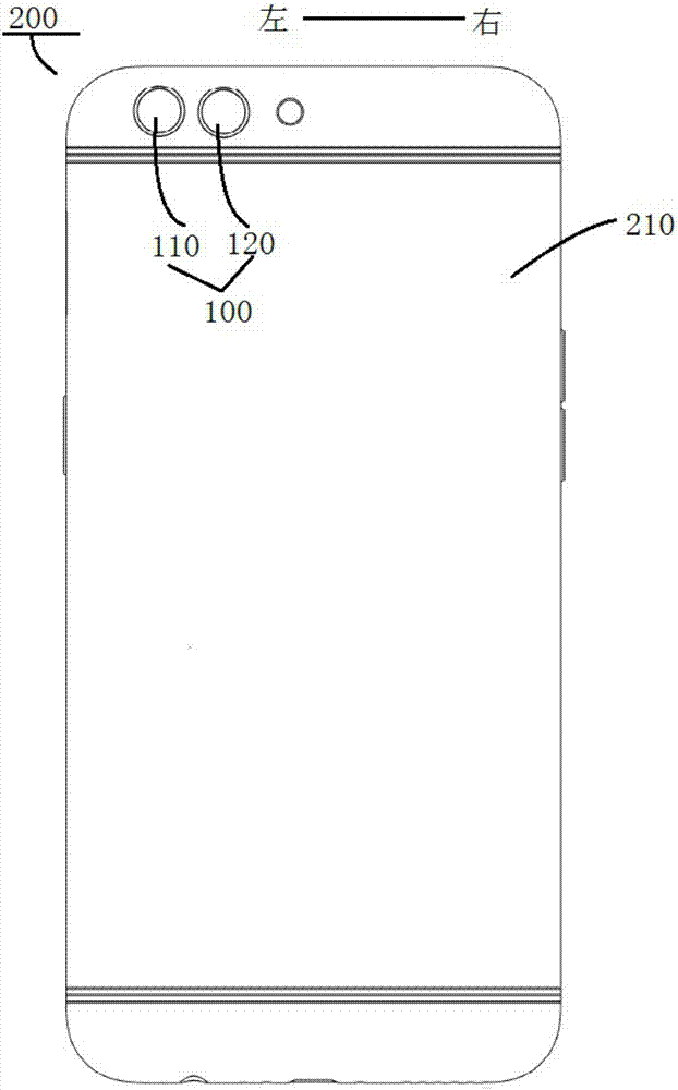
The invention discloses a camera component and electronic equipment. The camera component comprises a static camera, a moving camera and a driving part, wherein the moving camera can move relative to the static camera to adjust the distance between the moving camera and the static camera, and the driving part is connected with the moving camera to drive the moving camera to move. According to the camera component disclosed by the invention, the distance between the static camera and the moving camera can be adjusted, and thus the center deviation of viewing angles can be reduced, the ranging accuracy effect of the depth of field can be improved, the background blurring effect can be improved, and the imaging effect of the camera component can be further enhanced.

Description

technical field [0001] The present invention relates to the technical field of communication equipment, in particular, to a camera assembly and electronic equipment. Background technique [0002] In related technologies, configuring multiple cameras on electronic devices has gradually become the mainstream configuration of mobile phones. However, the distance between the two cameras on the market is too short, the deviation of the center of view angle is small, and the composite effect is better. The accuracy effect is poor, and the background blur effect is not good; the distance is too far, the depth-of-field ranging accuracy is high, and the background blur effect is good, but the center of view angle deviates greatly, and the composite effect deviates. Contents of the invention [0003] The present invention aims to solve at least one of the technical problems existing in the prior art. For this reason, the present invention proposes a camera assembly, which has the a...

Claims


Application Information

Patent Timeline
Patent Type & Authority Applications(China)
IPC IPC(8): H04N5/225H04N5/232
CPCH04N23/50H04N23/57H04N23/51H04N23/60
Inventor 李龙佳
Owner GUANGDONG OPPO MOBILE TELECOMM CORP LTD
Learn More