Attaching method and device for polarizers

A polarizer attachment and polarizer technology, applied in optics, nonlinear optics, instruments, etc., can solve the problems of not taking into account, poor product contrast performance, and failure to fully match the polarizing angle with the polarizing angle of the polarizer. Display the effect of good performance and accurate size

Inactive Publication Date: 2017-08-18
BOE TECH GRP CO LTD +1
View PDF5 Cites 6 Cited by
  • Summary
  • Abstract
  • Description
  • Claims
  • Application Information

AI Technical Summary

Problems solved by technology

Since this bonding method does not match the actual polarization axis of the polarizer with the polarization axis of the liquid crystal cell, nor does it take into account the influence of the manufacturing process and cutting accuracy on the polarization axis during the production of the polarizer, even if the edge of the polarizer is aligned with the The design mark is aligned and attached, and the polarization angle of the actual liquid crystal cell and the polarization angle of the polarizer are not completely consistent, resulting in that the optical characteristics of the product after the polarizer is attached cannot reach the design value, and the contrast performance of the product is poor.

Method used


Image

  • Attaching method and device for polarizers
  • Attaching method and device for polarizers
  • Attaching method and device for polarizers

Examples


Embodiment Construction

[0052] In order to make the above objects, features and advantages of the present invention more comprehensible, the present invention will be further described in detail below in conjunction with the accompanying drawings and specific embodiments.

[0053]In the description of the present invention, unless otherwise stated, the meaning of "plurality" is two or more; the terms "upper", "lower", "left", "right", "inner", "outer" The orientation or positional relationship indicated by etc. is based on the orientation or positional relationship shown in the drawings, and is only for the convenience of describing the present invention and simplifying the description, rather than indicating or implying that the machine or element referred to must have a specific orientation, use a specific Azimuth configuration and operation, therefore, should not be construed as limiting the invention.

[0054] In the description of the present invention, it should be noted that unless otherwise s...


PUM


Abstract

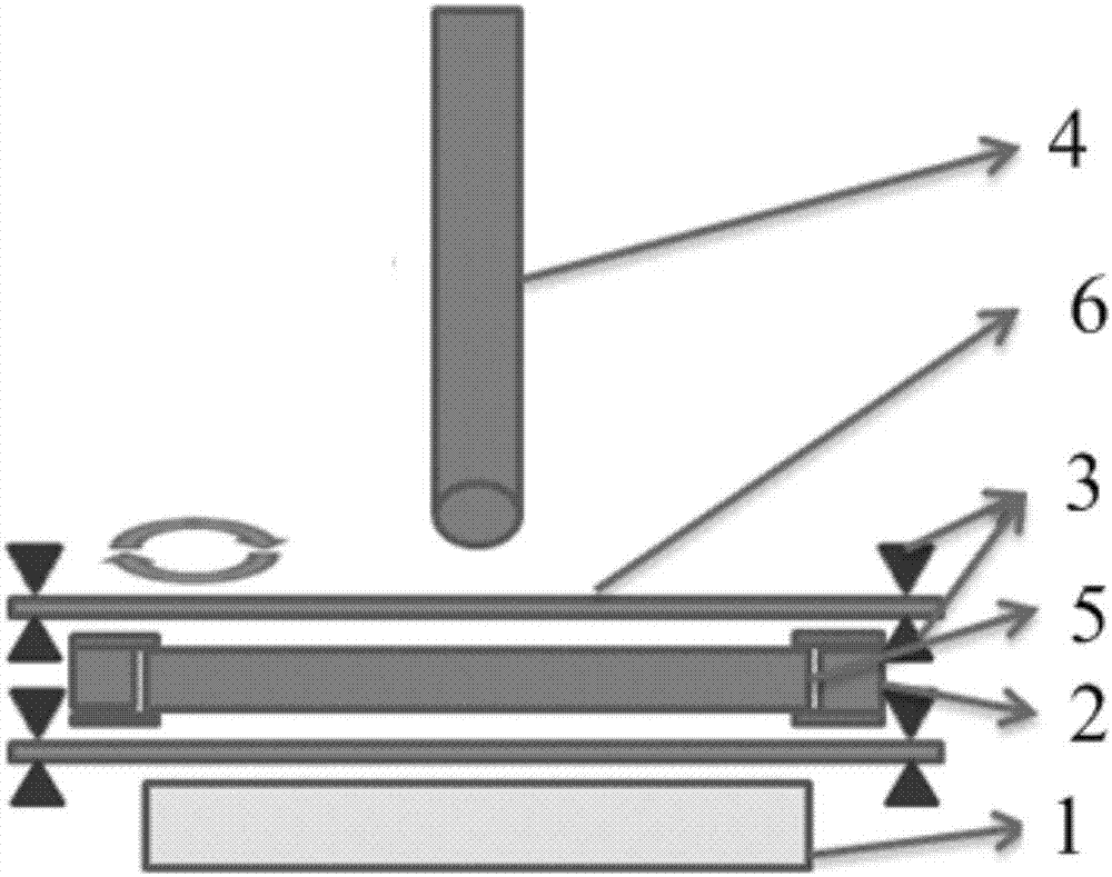
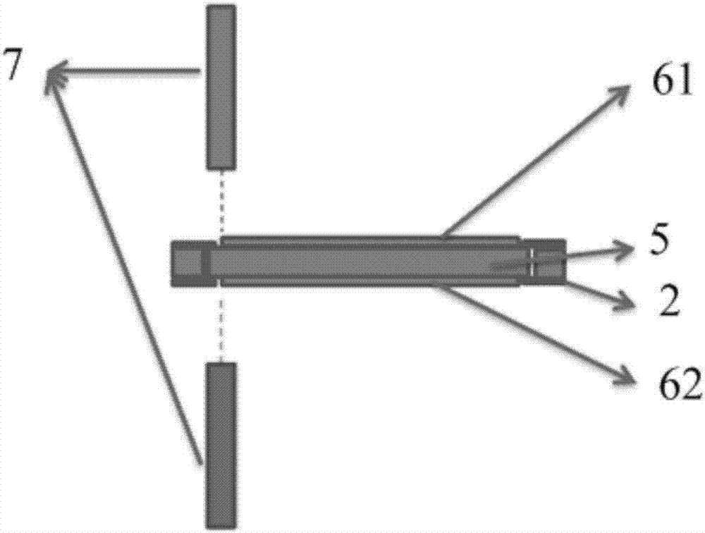
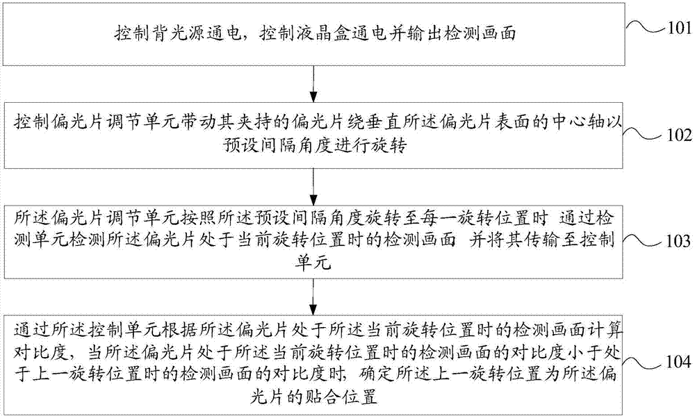
The invention provides an attaching method and device for polarizers. The equipment comprises a backlight source, a liquid crystal box fixing unit, a polarizer adjusting unit, a detection unit and a control unit. When the polarizer attaching device works, the backlight source is electrified and a liquid crystal box is electrified to output detection images. The polarizer adjusting unit drives the polarizers to rotate around the central shafts of surfaces of the polarizers at the pre-set interval angles. The detection unit detects detection images of the polarizers at the current rotary position and transmits the detection images to the control unit. The contrast ratios are calculated according to the detection images of the polarizers at the current rotary position by the control unit. When the contrast ratios of the polarizers at the current rotary position are less than those of the detection images of the polarizers at the former rotary position, a judgment is made that polarization angles of the polarizers at the former rotary position highly coincide with the polarization angle of the liquid crystal box so that the attachment positions of polarizers at the current rotary position are determined. The attached products possess high contrast performance.

Description

technical field [0001] The invention relates to the field of display technology, in particular to a method and equipment for attaching a polarizer. Background technique [0002] With the development of display technology, Thin Film Transistor Liquid Crystal Display (abbreviated as TFT-LCD) has been widely used due to its superior performances such as high quality and low power consumption. Polarizer is an important component in the structure of TFT-LCD, and its function is to realize the polarization of natural light. In the TFT-LCD manufacturing process, the attachment of polarizers has become an important process. [0003] With the existing polarizer attachment equipment, the attachment accuracy is mainly determined according to the distance between the shape of the polarizer and the edge of the liquid crystal cell. Since this bonding method does not match the actual polarization axis of the polarizer with the polarization axis of the liquid crystal cell, nor does it tak...

Claims


Application Information

Patent Timeline
IPC IPC(8): G02F1/13G02F1/1335
CPCG02F1/1303G02F1/133528
Inventor 张龙陈杰陈维诚管礼志
Owner BOE TECH GRP CO LTD
Why Eureka
Try Eureka