Eureka AIR delivers breakthrough ideas for toughest innovation challenges, trusted by R&D personnel around the world.

Method and system for calibrating optical axis of laser path

A technology of optical path and optical axis, applied in the field of optics, can solve problems such as inconvenience, lack, and lens error

Inactive Publication Date: 2017-08-18
NINGBO ONSIGHT CO LTD
View PDF4 Cites 9 Cited by
  • Summary
  • Abstract
  • Description
  • Claims
  • Application Information

AI Technical Summary

Problems solved by technology

The use of multiple lenses is more likely to bring errors, and the complex structure also brings great inconvenience to the calibration work, and operating these complex structures to calibrate the optical axis of the optical system also requires a considerable degree of professional knowledge
Ordinary lidar users may lack calibration components and skills training to perform calibration and cannot complete the calibration work by themselves. Therefore, providing an easy-to-operate and intuitive optical axis adjustment method can provide users with more convenience.

Method used


Image

  • Method and system for calibrating optical axis of laser path
  • Method and system for calibrating optical axis of laser path
  • Method and system for calibrating optical axis of laser path

Examples


Embodiment Construction

[0018] Various aspects of the illustrative embodiments herein are described below using terms commonly used by those skilled in the art to convey the substance of their work to others skilled in the art. It will be apparent, however, to those skilled in the art that alternative embodiments may be practiced using only some of the described aspects. For purposes of explanation, specific values, materials and configurations are set forth herein to facilitate understanding of the illustrative embodiments. It will be apparent, however, to one skilled in the art that alternative embodiments herein may be practiced without the specific details. In other instances, well-known features may be omitted or simplified in order not to obscure the embodiments herein.

[0019] Additionally, various operations will be described herein as multiple discrete operations in turn, in a manner that is most helpful in understanding the illustrative embodiments. However, the order described should no...


PUM


Abstract

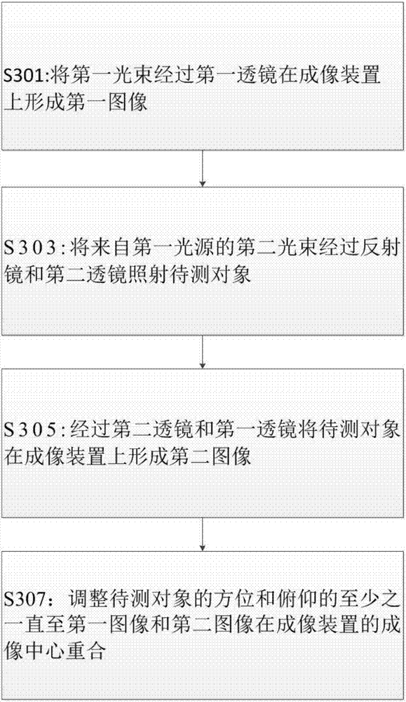
An embodiment of the invention relates to a method for calibrating an optical path of a laser path. The method comprises the steps of forming a first image on an imaging device from a first light beam through a first lens, irradiating a to-be-measured object by a second light beam from a first light source through a reflector and a second lens, and forming a second image of the to-be-measured object on the imaging lens through the second lens and the first lens; and adjusting at least one in direction and pitch of the to-be-measured object until the first image is superposed with the second image at the imaging center of the imaging device.

Description

technical field [0001] The invention belongs to the field of optical technology, and in particular relates to a calibration method and system for realizing the parallel or common optical axis of the optical axis of the laser receiving and receiving optical path. Background technique [0002] In the field of laser detection, it is often necessary to emit laser light to irradiate the target and receive the laser signal returned from the target to detect the target to be detected. Only by aligning the common optical axis or parallel optical axis of the laser emitting and receiving optical paths can sufficient accuracy of distance measurement or target detection be ensured. Therefore, the parallel or common optical axis calibration of the laser receiving and transmitting light path has always been one of the problems that must be faced in the field of laser ranging. At present, the traditional common optical axis calibration is calibrated by comparing the small hole diaphragm w...

Claims


Application Information

Patent Timeline
Patent Type & Authority Applications(China)
IPC IPC(8): G01S7/497
CPCG01S7/497G01S7/4972
Inventor 牛林全董利军何浩东朱少岚
Owner NINGBO ONSIGHT CO LTD
Why Eureka
Eureka Blog
Learn More