
Rail vehicle commissioning system, rail vehicle and rail vehicle commissioning method

A rail vehicle and debugging system technology, which is applied in the field of EMU single-car debugging, can solve the problems of inability to realize standard EMU electrical circuit test verification, narrow debugging range, and low efficiency, so as to improve vehicle debugging efficiency and reduce vehicle debugging cycle Effect

Active Publication Date: 2019-11-08
CRRC QINGDAO SIFANG CO LTD
View PDF7 Cites 0 Cited by
  • Summary
  • Abstract
  • Description
  • Claims
  • Application Information

AI Technical Summary

Problems solved by technology

[0005] The embodiment of the present invention provides a rail vehicle debugging system, a rail vehicle and a rail vehicle debugging method, to at least solve the problem in the prior art that the EMU single-car debugging range is narrow and the efficiency is low, and it is impossible to realize all the test verifications of the standard EMU electrical circuit technical issues

Method used


Image

  • Rail vehicle commissioning system, rail vehicle and rail vehicle commissioning method
  • Rail vehicle commissioning system, rail vehicle and rail vehicle commissioning method
  • Rail vehicle commissioning system, rail vehicle and rail vehicle commissioning method

Examples


Embodiment 1

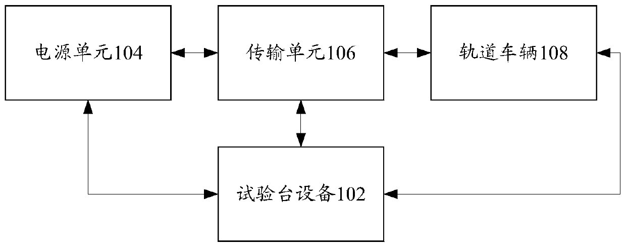
[0023] According to an embodiment of the present invention, an embodiment of a rail vehicle debugging system is provided, figure 1 is a system structure diagram according to an embodiment of the present invention, such as figure 1 As shown, the system includes: test bench equipment 102 , power supply unit 104 , transport unit 106 and rail vehicle 108 .

[0024] The test bench equipment 102 is connected to the rail vehicle, and is used to process the collected electrical signals of the rail vehicle to obtain control signals.

[0025] The power supply unit 104 is connected to the test bench equipment and the transmission unit respectively, and is used for supplying power to the test bench equipment and the transmission unit.

[0026] The transmission unit 106 is connected between the test bench equipment and the rail vehicle, and is used to transmit the control signal generated by the test bench equipment to the rail vehicle.

[0027] Specifically, such as figure 1 As shown, ...

Embodiment 2

[0082] According to an embodiment of the present invention, an embodiment of a rail vehicle debugging method is provided, Figure 6 is a schematic diagram of a method according to an embodiment of the present invention, such as Figure 6 As shown, the method includes the following steps:

[0083] In step S602, the electrical signal of the rail vehicle is collected through the test bench equipment, and the electrical signal is processed to obtain a control signal.

[0084] Step S604, transmitting the control signal generated by the test bench equipment to the rail vehicle through the transmission unit, wherein the power supply unit connected to the test bench equipment and the transmission unit supplies power to the test bench equipment and the transmission unit.

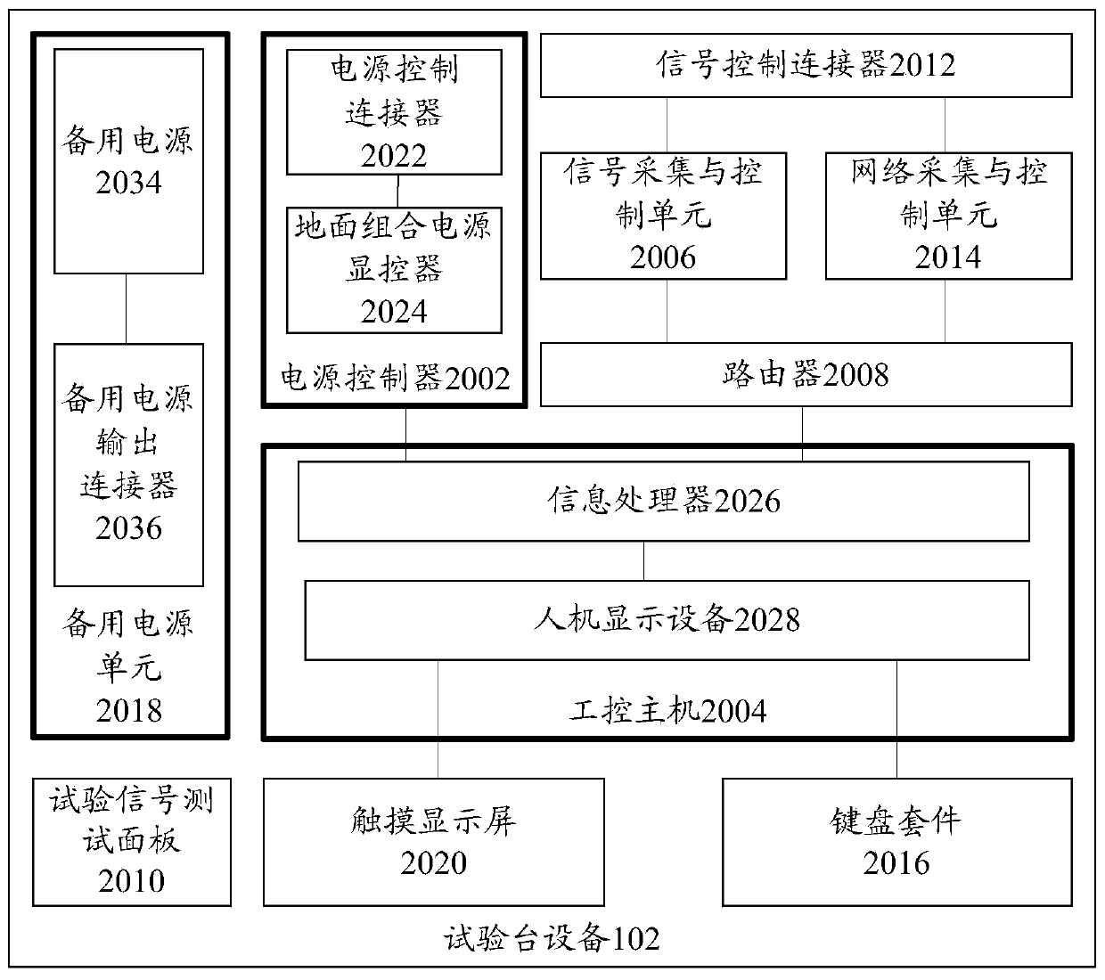
[0085] Specifically, the router in the test bench equipment obtains the electrical signal of the rail vehicle through the Ethernet network, and the signal acquisition and control unit and the network acquisition and...


PUM


Abstract

The invention discloses a track vehicle debugging system, a track vehicle and a track vehicle debugging method. The system comprises a test bench device, a transmission unit, and a power supply unit, wherein the test bench device is connected with the track vehicle for processing acquired electrical signals of the track vehicle to obtain control signals; the transmission unit is connected between the test bench device and the track vehicle for transferring the control signals generated by the test bench device to the track vehicle; and the power supply unit is connected with the test bench device and the transmission unit respectively for providing power for the test bench device and the transmission unit. The technical problems that a single unit in a train set has a narrow range and low efficiency in the prior art, and all test verification on the electrical loop of the standard train set can not be realized can be solved.

Description

technical field [0001] The invention relates to the field of single-car debugging of EMUs, in particular to a rail vehicle debugging system, a rail vehicle and a rail vehicle debugging method. Background technique [0002] With the continuous acceleration of people's life rhythm, in order to save time, people have higher requirements for speed, so EMUs with faster speed and more comfortable environment appear. In order to ensure the safe and efficient operation of the EMU, it is necessary to debug the single vehicle of the EMU. [0003] Existing EMU single-car commissioning only conducts conduction and withstand voltage tests on EMU vehicle cables, and does not conduct vehicle system power supply tests. After the completion of some vehicle assembly processes, it waits for other vehicle marshalling tests, which not only occupies the EMU platform, but also affects the entire train. debug cycle. Moreover, the standard EMU is a newly designed EMU platform, which is quite diffe...

Claims


Application Information

Patent Timeline
Patent Type & Authority Patents(China)
IPC IPC(8): G01R31/00
CPCG01R31/008
Inventor 邴晨阳侯晓宝常杰徐顺郑启亮沈华波
Owner CRRC QINGDAO SIFANG CO LTD
Learn More