
Multifunctional supporting base

A support base, multi-functional technology, applied in the direction of supporting machines, machines/brackets, mechanical equipment, etc., can solve problems such as unreliable fixation, increased space occupied by equipment, and small contact surface of universal wheels

Active Publication Date: 2017-08-18
WUHU TIANREN INTELLIGENT MACHINERY
View PDF8 Cites 3 Cited by
  • Summary
  • Abstract
  • Description
  • Claims
  • Application Information

AI Technical Summary

Problems solved by technology

When the equipment is moved to the designated position, the base needs to be fixed. In the prior art, foot brakes are generally installed on the universal wheels, and the universal wheels are locked by the foot brakes to fix the base. However, the universal wheels are in contact with the ground. The small surface makes the fixation unstable and in some environments it is impossible to lock all the universal wheels on the base at the same time
For some large-scale equipment, in order to ensure the reliability of the base, there are also multiple fixed piles arranged at intervals under the base. When the equipment moves to the designated position, the driving mechanism is used to drive the fixed piles to move down and touch the ground, and then Support the base to improve the reliability of the equipment support. However, in order to ensure that the center of gravity of the equipment is placed within the range of the contact surface between the fixed pile and the ground, the fixed pile is generally set near the outside of the equipment, which increases the occupied space of the equipment. Not suitable for small devices

Method used


Image

  • Multifunctional supporting base
  • Multifunctional supporting base
  • Multifunctional supporting base

Examples


Embodiment Construction

[0024] combine Figure 1 to Figure 6 , the present invention is further described:

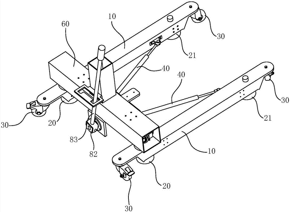
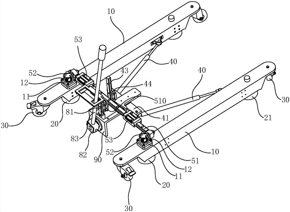
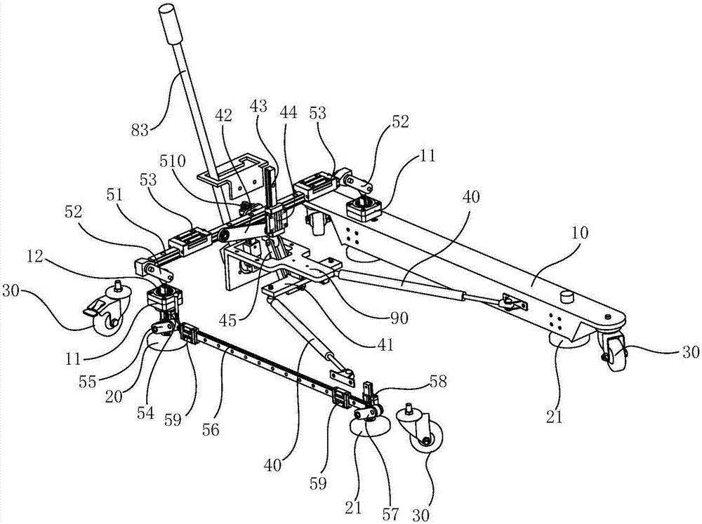
[0025] A multifunctional support base, the base is composed of at least two support rods 10, the rod length direction of the support rods 10 is horizontal and in the same horizontal plane, the support rods are provided with proximal support feet 20 and Far-end supporting foot 21, described base is provided with driving mechanism, and driving mechanism drives near-end supporting foot 20 and far-end supporting foot 21 to move up and down and the lower end of near-end supporting foot 20 and far-end supporting foot 21 is separated from the ground or against By the way, the base is also provided with a linkage mechanism, and the linkage mechanism drives the support rods 10 to rotate around the proximal support legs 20 respectively. The vertical movement of the proximal support leg 20 and the distal support leg 21 cooperates with the rotation of the support rod 10 around the proximal support leg 20...


PUM


Abstract

The invention relates to a multifunctional supporting base. The base is at least composed of two supporting rods. The rod length direction of each supporting rod is horizontal, and the supporting rods are located in the same horizontal plane. Multiple supporting feet are arranged on each supporting rod. A drive mechanism is arranged on the base and drives the supporting feet to move up and down, and the lower ends of the corresponding supporting feet are separated from or abut against the ground. A linkage mechanism is further arranged on the base and drives the supporting rods to rotate around the corresponding supporting feet. Up-and-down movement of the supporting feet is matched with rotation of the supporting rods around the corresponding supporting feet. When the base needs to be fixed, the supporting feet are driven by the drive mechanism to move downwards to abut against the ground, and supporting on the base is achieved; and in the process that the supporting feet move downwards, the supporting rods on the base are synchronously driven by the linkage mechanism to rotate around the corresponding supporting feet, and therefore the area between the two supporting rods can be increased, it can be ensured that the gravity center of equipment is located between the two supporting rods, the supporting stability of the base on the equipment can be enhanced, and the supporting feet arranged telescopically cannot influence normal movement of the base.

Description

technical field [0001] The invention relates to the technical field of mechanical equipment support, in particular to a multifunctional support base. Background technique [0002] Many devices in the prior art are arranged on a base. In order to facilitate the movement of the device, universal wheels are generally provided under the base, so that the device can be moved from one position to another conveniently. When the equipment is moved to the designated position, the base needs to be fixed. In the prior art, foot brakes are generally installed on the universal wheels, and the universal wheels are locked by the foot brakes to fix the base. However, the universal wheels are in contact with the ground. The small surface makes the fixation unstable and in some environments it is impossible to lock all the universal wheels on the base at the same time. For some large-scale equipment, in order to ensure the reliability of the base, there are also multiple fixed piles arranged...

Claims


Application Information

Patent Timeline
IPC IPC(8): F16M11/42
CPCF16M11/42
Inventor 王勇陈楠李志强杨岩江刘正士
Owner WUHU TIANREN INTELLIGENT MACHINERY
Learn More