
Bridge erecting machine for precast segmental beam span by span construction and construction method thereof

A technology for segment beams and bridge erection machines, which is applied in the directions of bridges, bridge construction, erection/assembly of bridges, etc., can solve problems such as increased labor costs, complex construction conditions, and reduced construction work efficiency.

Active Publication Date: 2017-08-18
ZHENGZHOU NEW DAFANG HEAVY IND & TECH
View PDF6 Cites 30 Cited by
  • Summary
  • Abstract
  • Description
  • Claims
  • Application Information

AI Technical Summary

Problems solved by technology

However, since there are many sensitive areas such as roads, natural water source protection areas, and military facilities distributed along the railway line, and the construction conditions are complex, higher requirements are placed on the ability of the bridge erecting machine to adapt to the line.
[0003] Although bridge erecting machines have been widely used in high-speed railway construction at this stage, there are unavoidable shortcomings:
[0004]1. In the construction of prefabricated segmental beams with wet joints, the existing bridge erecting machine needs to manually install and remove the formwork when pouring the wet joints. Low efficiency and increased labor costs;
[0005]2. During the construction of the existing bridge erecting machine, due to the limitation of conditions, the beam transport vehicle feeds the beam from the back of the bridge, and the prefabricated segmental beam is fully hung on the bottom of the main frame Sometimes it needs to be placed in staggered layers, which reduces the construction efficiency; after the entire span section beam is stretched, it is necessary to use hydraulic jacks to unload the boom load one by one, which reduces the safety performance;
[0006]3. The outriggers of the existing bridge erecting machine are supported at the top of the pier, and the local tension holes interfere with the outriggers. Tensioning will affect the construction efficiency;
[0007]4. When the existing bridge erecting machine passes through the hole, it needs to increase the counterweight to improve the longitudinal stability of the whole machine, and the support of a large-tonnage crane is required to change the position of the outrigger

Method used


Image

  • Bridge erecting machine for precast segmental beam span by span construction and construction method thereof
  • Bridge erecting machine for precast segmental beam span by span construction and construction method thereof
  • Bridge erecting machine for precast segmental beam span by span construction and construction method thereof

Examples


Embodiment Construction

[0118] The direction of the arrow in the accompanying drawings indicates the erection direction of the bridge erecting machine construction method used for the span-by-span construction of the prefabricated segmental beams.

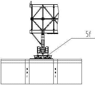
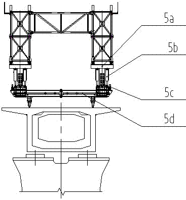
[0119] Such as figure 1 As shown, the bridge erecting machine used for the span-by-span construction of prefabricated segmental beams includes the main frame 1, outrigger system, hanging system, wet joint formwork system and crown block system. The outrigger system includes longitudinal The No. 1 outrigger 2, the No. 2 outrigger 3, the No. 3 outrigger 4 and the No. 4 outrigger 5 are arranged in sequence from front to back, wherein the No. 1 outrigger 2 and the No. 4 outrigger 5 are respectively located on the two sides of the main frame 1 The end is used as an auxiliary support leg, the second leg 3 and the third leg 4 are heavy-duty support legs, the hanging system is connected to the bottom of the main frame 1, and the wet joint formwork system is conne...


PUM


Abstract

The invention discloses a bridge erecting machine for precast segmental beam span by span construction and a construction method thereof. The bridge erecting machine for the precast segmental beam span by span construction comprises a main frame, a support leg system, a hanging system, a wet joint template system and an overhead travelling crane system. The support leg system comprises a number one support leg, a number two support leg, a number three support leg and a number four support leg, which sequentially arranged at the lower portion of the main frame from front to back, wherein the number one support leg and the number four support leg are located on two ends of the main frame as a auxiliary supporting support leg correspondingly, the number two support leg and the number three support leg are used as a heavy load supporting support leg, the hanging system is connected to the bottom of the main frame, the wet joint template system is connected to the outside of the main frame, the overhead travelling crane system is arranged on a longitudinal moving rail at the top of the main frame; and the construction method of the bridge erecting machine for precast segmental beam span by span construction comprises beam erecting process of the bridge erecting machine and bridge erecting machine through-hole process. The bridge erecting machine for the precast segmental beam span by span construction and the construction method thereof have the advantages that the construction demands of the precast segmental beam of high speed railway are met, the construction efficiency is high, and the construction is convenient and highly efficient.

Description

technical field [0001] The invention relates to the technical field of high-speed railway construction, in particular to a bridge erecting machine for span-by-span construction of prefabricated segmental beams and a construction method thereof. Background technique [0002] With the rapid development of science and technology and infrastructure in our country, especially in the construction of high-speed railways, various types of bridge erecting machines have been widely used, which has improved the construction speed and quality of railways. However, since there are many sensitive areas such as highways, natural water source protection areas, and military facilities distributed along the railway line, and the construction conditions are complex, higher requirements are placed on the ability of the bridge erecting machine to adapt to the line. [0003] Although bridge erecting machines have been widely used in high-speed railway construction at this stage, their shortcoming...

Claims


Application Information

Patent Timeline
Patent Type & Authority Applications(China)
IPC IPC(8): E01D21/00
CPCE01D21/00
Inventor 张志华陈德利宋飞代宇周治国张俊艳刘舒馨张永力牛青林程波高建华祖国栋李军超向光波王雪朋
Owner ZHENGZHOU NEW DAFANG HEAVY IND & TECH
Learn More