
Electric wave receiving antenna used for tire pressure monitoring system and tire pressure monitoring system

A tire pressure and radio wave receiving technology, which is applied in tire measurement, tire parts, transportation and packaging, etc., can solve the problems that the receiver cannot receive the signal and the received signal is poor, so as to improve driving safety, simple structure and accurate transmission Effect

Inactive Publication Date: 2017-08-18
SHANGHAI VEI SHENG AUTO PARTS MFG CO LTD
View PDF10 Cites 0 Cited by
  • Summary
  • Abstract
  • Description
  • Claims
  • Application Information

AI Technical Summary

Problems solved by technology

When there is a metal cover next to the receiving antenna, the electromagnetic wave emitted by the detection module will be reflected back, resulting in the receiver not receiving the signal or receiving poor signal

Method used


Image

  • Electric wave receiving antenna used for tire pressure monitoring system and tire pressure monitoring system
  • Electric wave receiving antenna used for tire pressure monitoring system and tire pressure monitoring system
  • Electric wave receiving antenna used for tire pressure monitoring system and tire pressure monitoring system

Examples


Embodiment Construction

[0045] In order to more clearly illustrate the embodiments of the present invention or the technical solutions in the prior art, the specific implementation manners of the present invention will be described below with reference to the accompanying drawings. Obviously, the accompanying drawings in the following description are only some embodiments of the present invention, and those skilled in the art can also obtain other accompanying drawings based on these drawings and obtain other implementations.

[0046] In order to make the drawing concise, each drawing only schematically shows the parts related to the present invention, and they do not represent the actual structure of the product. In addition, to make the drawings concise and easy to understand, in some drawings, only one of the components having the same structure or function is schematically shown, or only one of them is marked. Herein, "a" not only means "only one", but also means "more than one". in addition, ...


PUM


Abstract

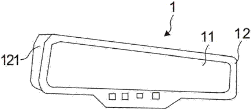
The invention provides an electric wave receiving antenna used for a tire pressure monitoring system and the tire pressure monitoring system. The antenna comprises a rearview mirror; the rearview mirror comprises a view mirror body and a shell covering the periphery of the view mirror body; a containing space is formed between the view mirror body and the shell in a partitioning mode; a circuit board is arranged in the containing space; the shell is of an antenna structure provided with a metal radiation element connected with the circuit board; and the metal radiation element is in a face shape or a strip shape and is arranged on the outer surface of the shell. The tire pressure monitoring system comprises a receiver, the antenna used for receiving and sending signals, a sensor mounted on an automobile tire and a display used for displaying information received by the receiver. The electric wave receiving antenna and the tire pressure monitoring system can be matched with the new network technology, it can be also guaranteed that the signals transmitted by the electric wave receiving antenna are not liable to be disturbed and can be transmitted timely and accurately.

Description

technical field [0001] The invention relates to the technical field of tire pressure monitoring, in particular to an antenna for receiving electric waves used for a tire pressure monitor and the tire pressure monitor. Background technique [0002] With the progress of society and the improvement of people's living standards, automobiles have become the basic means of transportation for people, and people pay more and more attention to driving safety issues. According to statistics, 46% of traffic accidents on China's expressways are caused by tire failures, and 70% of them are directly blown out, which poses a great threat to people's lives and property safety, and tire pressure monitors were born. [0003] Tire Pressure Monitoring System (TPMS for short) is a wireless transmission technology that uses a high-sensitivity miniature wireless sensor device fixed in the car tire to collect car tire pressure, temperature, etc. data, and transmit the data to the host computer in ...

Claims


Application Information

Patent Timeline
Patent Type & Authority Applications(China)
IPC IPC(8): B60C23/04
CPCB60C23/0444
Inventor 尤山泉林东峰洪松辉蔡峻丞郭振华
Owner SHANGHAI VEI SHENG AUTO PARTS MFG CO LTD
Learn More