
A self-rotating pneumatic slitting knife

A slitting knife and rotating shaft technology, applied in metal processing and other directions, can solve the problems of inability to adjust the gap between the upper knife and the lower knife, the speed of the upper knife cannot be accurately controlled, and the use and operation are inflexible. Blunt, maintenance cost saving, cleverly structured effect

Active Publication Date: 2019-04-12
美塞斯(珠海)工业自动化设备有限公司
View PDF8 Cites 0 Cited by
  • Summary
  • Abstract
  • Description
  • Claims
  • Application Information

AI Technical Summary

Problems solved by technology

[0002] At present, pneumatic or electronic slitting knives are a kind of processing equipment commonly used in cutting thin and long sheet materials in the coil processing industry. The upper blades of the slitting knives sold on the market are all without driving power. The knife exerts a certain lateral force against the knife and is driven by the active rotating lower knife through friction. The upper and lower blades are prone to bluntness and damage. The speed of the upper knife cannot be precisely controlled, and the cutting performance is poor, so it is not suitable for low Tension-sensitive materials are used, and the service life is extremely short, requiring frequent replacement, which greatly increases maintenance costs
In addition, the blades of these existing cutting knives cannot adjust the gap between the upper knife and the lower knife according to the cutting requirements, and the operation is extremely inflexible and inconvenient

Method used


Image

  • A self-rotating pneumatic slitting knife
  • A self-rotating pneumatic slitting knife
  • A self-rotating pneumatic slitting knife

Examples


Embodiment Construction

[0022] In order to make the object, technical solution and advantages of the present invention clearer, the present invention will be further described in detail below in conjunction with the accompanying drawings and embodiments. It should be understood that the specific embodiments described here are only used to explain the present invention, not to limit the present invention.

[0023] Such as Figure 1 to Figure 5 as shown in:

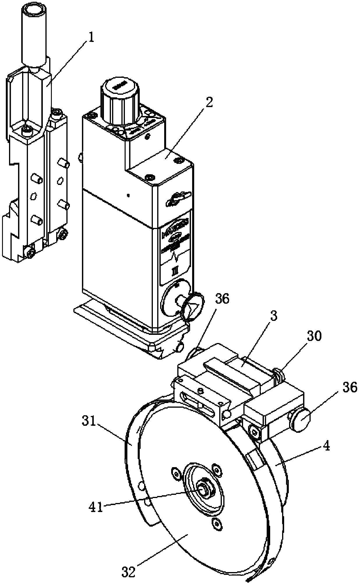
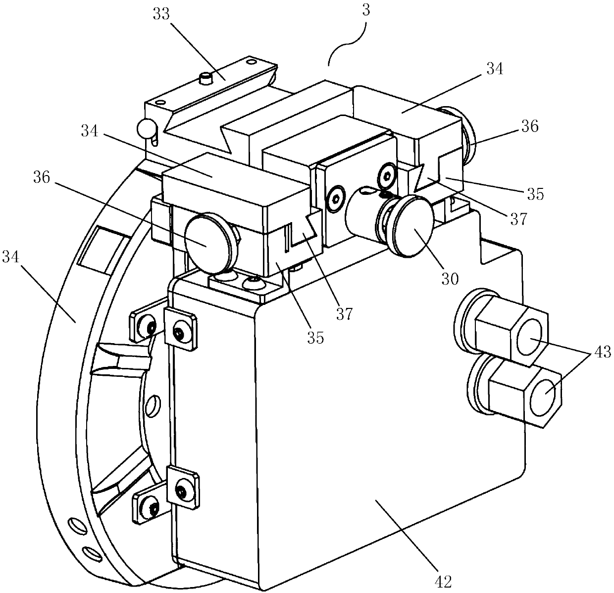
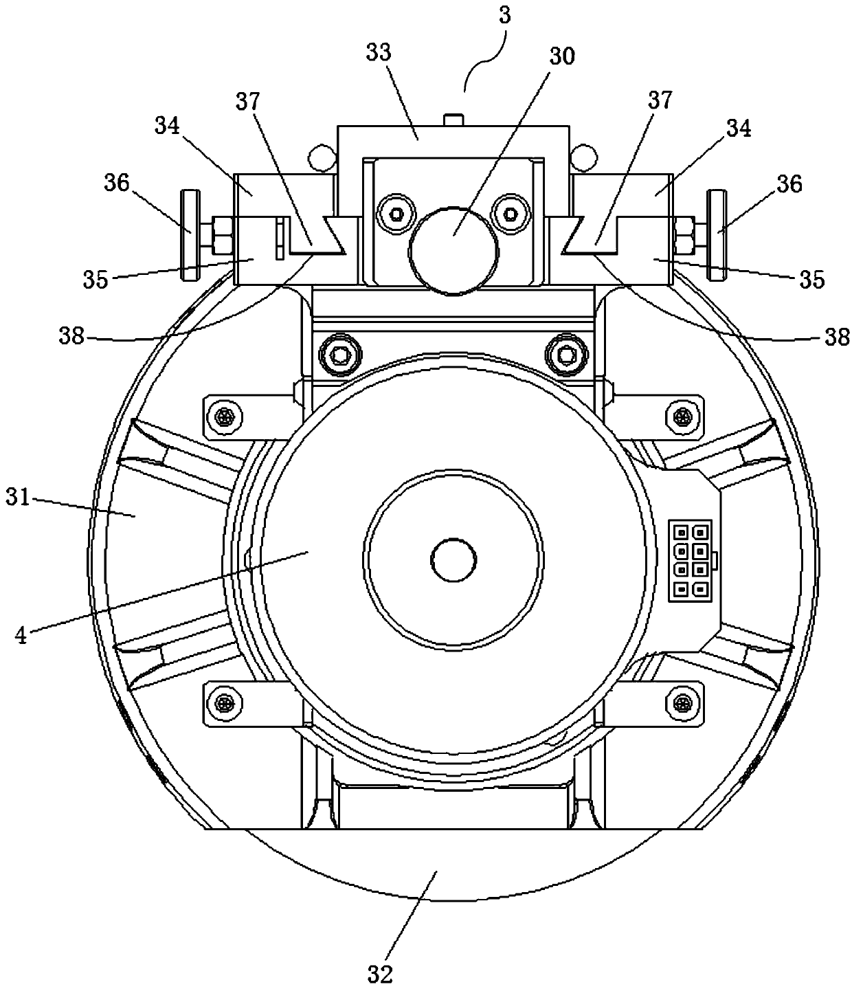
[0024] A self-rotating pneumatic slitting knife described in Embodiments 1 and 2 of the present invention includes a knife body composed of an installation backplane 1 and a control body 2, and a knife head assembly 3, and the knife head assembly 3 is assembled with the knife body The back of the cutter cover 31 of the cutter head assembly 3 is provided with a drive unit 4, and the drive unit 4 is drivingly connected with the blade 32 on the front of the cutter cover 31 to drive the blade 32 to rotate. Wherein, the drive unit 4 can be a drive mo...


PUM


Abstract

The invention provides an autorotation pneumatic slicing knife which comprises a knife body composed of an installation back plate and a control body and a knife bit assembly. A driving unit is arranged on the back face of a knife cover of the knife bit assembly and is in driving connection with blades on the front face of the knife cover so as to drive the blades to achieve autorotation motion. In this way, the slicing knife can drive the blades to rotate in the using process, the problem that an upper blade of a traditional slicing knife is driven by a lower blade through friction force, the speed cannot be accurately controlled, and therefore the low-tension coiled material slicing effect is poor is solved, the problem that the blades are prone to being rubbed and becoming blunt is solved, the service life of the blades is longer, the replacement frequency is reduced, the maintaining cost is saved, and the slicing performance is more stable; in addition, the slicing knife further has the upper blade vertical direction fine adjustment function, the horizontal direction movement fine adjustment function and the like, fine adjustment of the cut depth and the left-right gap between the upper blade and the lower blade of the slicing cutter can be achieved according to the slicing requirement, use is flexible, and operation is simple, convenient and rapid; and in addition, the autorotation pneumatic slicing knife is ingenious, reasonable and scientific in structure and easy to produce and machine.

Description

【Technical field】 [0001] The invention belongs to the technical field of material cutting equipment, and in particular relates to a self-rotating pneumatic cutting knife. 【Background technique】 [0002] At present, pneumatic or electronic slitting knives are a kind of processing equipment commonly used in cutting thin and long sheet materials in the coil processing industry. The upper blades of the slitting knives sold on the market are all without driving power. The knife exerts a certain lateral force against the knife and is driven by the active rotating lower knife through friction. The upper and lower blades are prone to bluntness and damage. The speed of the upper knife cannot be precisely controlled, and the cutting performance is poor, so it is not suitable for low Tension-sensitive materials are used, and the service life is extremely short, requiring frequent replacement, which greatly increases maintenance costs. In addition, the blades of these existing slitting...

Claims


Application Information

Patent Timeline
Patent Type & Authority Patents(China)
IPC IPC(8): B26D1/24B26D7/26
CPCB26D1/245B26D7/2635
Inventor 杨奕能吴捷洲
Owner 美塞斯(珠海)工业自动化设备有限公司
Learn More