Interferometer for detecting point-diffraction wave aberration and its detection method

A wave aberration and interferometer technology, applied in the field of interferometry, can solve problems such as the inability to flexibly use the fringe carrier algorithm, the inability to achieve zero fringe detection, and the constraints on the use of interferometers.

Active Publication Date: 2019-02-26
SHANGHAI INST OF OPTICS & FINE MECHANICS CHINESE ACAD OF SCI
View PDF7 Cites 0 Cited by
  • Summary
  • Abstract
  • Description
  • Claims
  • Application Information

AI Technical Summary

Problems solved by technology

However, because this technical solution needs to place two point light sources on the object plane of the imaging system at the same time, due to the limitation of the spatial resolution of the photoelectric sensor, the two point light sources cannot be too far apart. Due to the noise problem of the light window of the point diffraction interferometer, a low The data measurement frequency band is limited by the pass filter, so that the measurement spatial resolution of the system is restricted (see prior art 2: Patrick P.Naulleau, Kenneth A.Goldberg, Dual-domain point diffraction interferometer, APPLIED OPTICS, 38(16), 3523-3533(1999).); Moreover, due to the use of dual-point light sources, the system cannot achieve zero fringe detection. When the phase-shift algorithm is used, it is more sensitive to noise factors such as vibration and phase shifter nonlinearity; on the other hand, the dual-point light source After the distance between point light sources is fixed, the number of interference fringes cannot be adjusted, and various interferometric data processing algorithms such as fringe carrier algorithm and space carrier phase shift algorithm cannot be flexibly used to improve the detection speed, which makes the use conditions of the interferometer subject to certain restrictions

Method used


Image

  • Interferometer for detecting point-diffraction wave aberration and its detection method
  • Interferometer for detecting point-diffraction wave aberration and its detection method
  • Interferometer for detecting point-diffraction wave aberration and its detection method

Examples


Embodiment Construction

[0048] The present invention will be further described below in conjunction with the accompanying drawings and embodiments, but the embodiments do not limit the protection scope of the present invention.

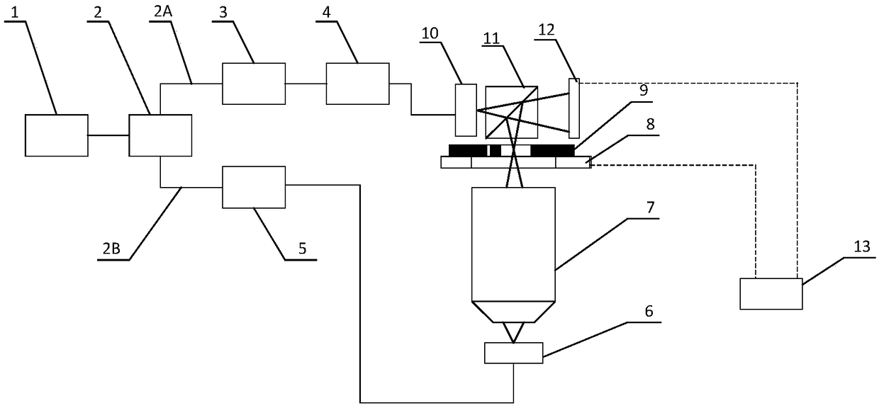
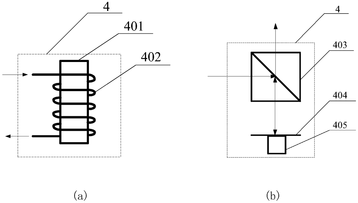
[0049] figure 1 It is a structural schematic diagram of the point-diffraction wave aberration detection interferometer of the present invention. The point-diffraction wave aberration detection interferometer of the present invention includes: a light source 1, a first beam splitter 2, a first light intensity and polarization state adjuster 3, and a phase shifter 4. The second light intensity and polarization state adjuster 5, the point light source generating unit 10, the ideal wavefront generating unit 6, the optical system to be tested 7, the precision adjustment table 8, the pinhole optical window device 9, the second beam splitter 11, the two-dimensional Photodetector 12 and data processing unit 13;

[0050] The positional relationship of the above parts is as follows: ...


PUM


Abstract

The invention relates to a point diffraction wave aberration detection interferometer and detection method. The interferometer comprises a light source, a first splitter, a first light intensity and polarization regulator, a phase shifter, a second light intensity and polarization regulator, a point light source generation unit, an ideal wavefront generation unit, a to-be-detected optical system, a precise adjusting table, a small aperture light window device, a second splitter, a two-dimensional photoelectric detector and a data processing unit. The interferometer is advantaged in that measurement space resolution is high, interference fringe density is adjustable, multiple interference phase extraction algorithms such as phase shift and space carrier wave phase shift can be utilized, an interferometer system error can be calibrated, and interference contrast is adjustable.

Description

technical field [0001] The invention relates to the field of interferometry, in particular to a point-diffraction interference wave aberration detection interferometer and a detection method thereof. Background technique [0002] Waveform aberration is an important parameter to describe the performance of small aberration imaging optical system. The wave aberration of high-quality microscope objectives and space telescopes should be less than λ / 4PV or λ / 14RMS (λ is the working wavelength, and RMS is the root mean square value). The wave aberration of deep ultraviolet lithography projection objective lens and extreme ultraviolet lithography projection objective lens should be less than 1nm RMS. This puts high demands on wave aberration detection technology. [0003] The prior art (refer to prior art 1: Tang Feng, Wang Xiangchao, etc., point diffraction interference wave aberration measuring instrument and detection method, invention patent 201310126148.5) proposes a point d...

Claims


Application Information

Patent Timeline
Patent Type & Authority Patents(China)
IPC IPC(8): G01M11/02
CPCG01M11/02
Inventor 唐锋王向朝冯鹏
Owner SHANGHAI INST OF OPTICS & FINE MECHANICS CHINESE ACAD OF SCI
Why Eureka
Try Eureka