Sealing structure

A technology of sealing structure and sealing ring, which is applied to the sealing device of piston pump, machine/engine, pump components, etc., can solve problems such as failure, and achieve the effect of improving sealing performance

Inactive Publication Date: 2017-08-11
SANDEN HUAYU AUTOMOTIVE AIR CONDITIONING CO LTD
View PDF9 Cites 0 Cited by
  • Summary
  • Abstract
  • Description
  • Claims
  • Application Information

AI Technical Summary

Problems solved by technology

[0003] However, when the commonly used O-rings are installed on instruments with high pressure in the cavity, failures still occur from time to time

Method used


Image

  • Sealing structure
  • Sealing structure
  • Sealing structure

Examples


Embodiment 1

[0033] This embodiment takes a scroll compressor as an example to illustrate the implementation of the sealing structure according to the present invention. In addition to the scroll compressor, the present invention can be applied between relatively stationary shells, covers, plates and other parts. , especially on instruments with high sealing requirements due to the pressure difference between the cavity and the atmosphere.

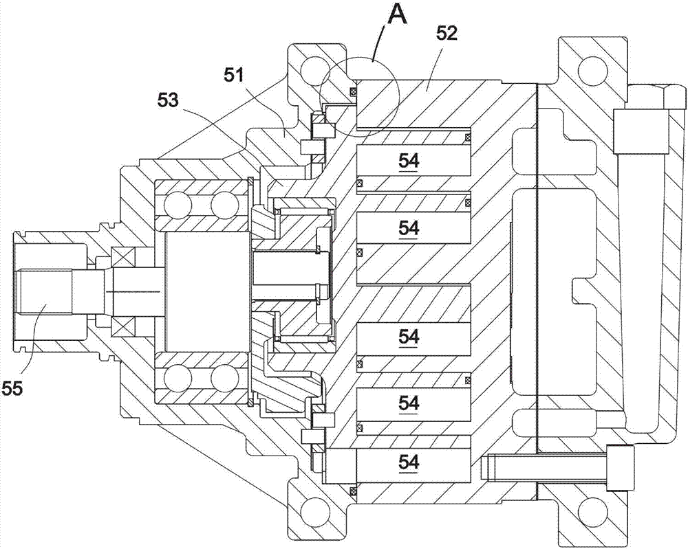
[0034] Such as picture 1 As shown, the compression assembly of the scroll compressor includes a movable scroll 53 and a fixed scroll 52 , which mesh with each other to enclose a plurality of compression chambers 54 . The fixed scroll 52 remains stationary, and the movable scroll 53 is driven by the crankshaft 55 to rotate eccentrically. The peripheral compression chamber 54 sucks the refrigerant, and the compression chamber 54 gradually moves to the center while shrinking in size. When it moves to the center, the refrigerant is discharged, thereby ...


PUM


Abstract

The invention aims at providing a sealing structure capable of improving the sealing performance of a sealing ring. The sealing structure comprises a first joint face and a second joint face which are in butt joint. One of the first joint face and the second joint face is provided with a groove, and a sealing piece is arranged in the groove. The sealing structure is characterized in that the sealing piece comprises a sealing ring body and a plurality of supporting convex ribs extending towards the inner side from the sealing ring body, the supporting convex ribs and the inner wall of the groove are pressed and attached, and the sealing ring body is expanded outwards and makes contact with the outer wall of the groove in an attached manner.

Description

technical field [0001] The present invention relates to a sealing mechanism, which is especially suitable for the sealing structure between the casings of compressors, or between the casing and parts statically assembled on the casing, for example, between the casing and the casing, and between the casing and the casing. Seal between suction and exhaust cover plates. Background technique [0002] Sealing structures such as gaskets and sealing rings are provided at the junction between the shells of the compressor to prevent leakage of gas and lubricating oil. Conventional sealing mechanisms such as O-rings are made of nitrile rubber and have a circular cross-section. When the shells are pressed against each other and assembled, the O-rings are squeezed by both sides and deformed. A larger contact area is generated between them to obtain a better sealing effect. [0003] However, when the commonly used O-ring is arranged on a device with high pressure in the cavity, failure...

Claims


Application Information

Patent Timeline
IPC IPC(8): F04C27/00
CPCF04C27/00
Inventor 杨瑞屠嘉伟李钢马骏房锦忠
Owner SANDEN HUAYU AUTOMOTIVE AIR CONDITIONING CO LTD
Why Eureka
Try Eureka