Lever-type inching limit switch

A limit switch and lever-type technology, which is applied in the field of switches, can solve the problems of large tolerances of action parameters, meet the requirements of extremely small tolerances, and avoid the effects of aging of elastic components

Active Publication Date: 2017-08-08
ZHANGZHOU JUANMEI ELECTRIC TECH CO LTD
View PDF7 Cites 4 Cited by
  • Summary
  • Abstract
  • Description
  • Claims
  • Application Information

AI Technical Summary

Problems solved by technology

[0009] Purpose of the invention: The purpose of the present invention is to address the deficiencies in the prior art and provide a lever-type micro-motion limit switch to solve the problem of large tolerances in its action parameters and at the same time solve the problem that the switch is close to the action point during the slow motion process. Often open connectors or normally closed connectors are not energized, or the switch signal flickers to ensure that industries, household appliances, transportation machines or equipment are safer and more reliable

Method used


Image

  • Lever-type inching limit switch
  • Lever-type inching limit switch
  • Lever-type inching limit switch

Examples


Embodiment Construction

[0033] The technical solutions of the present invention will be described in detail below, but the protection scope of the present invention is not limited to the embodiments.

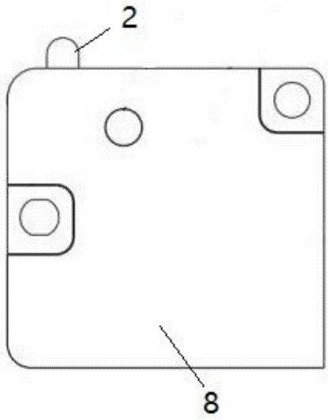
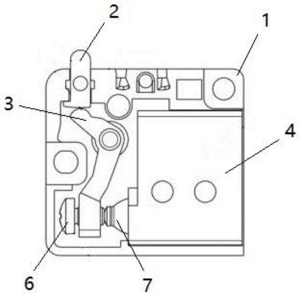
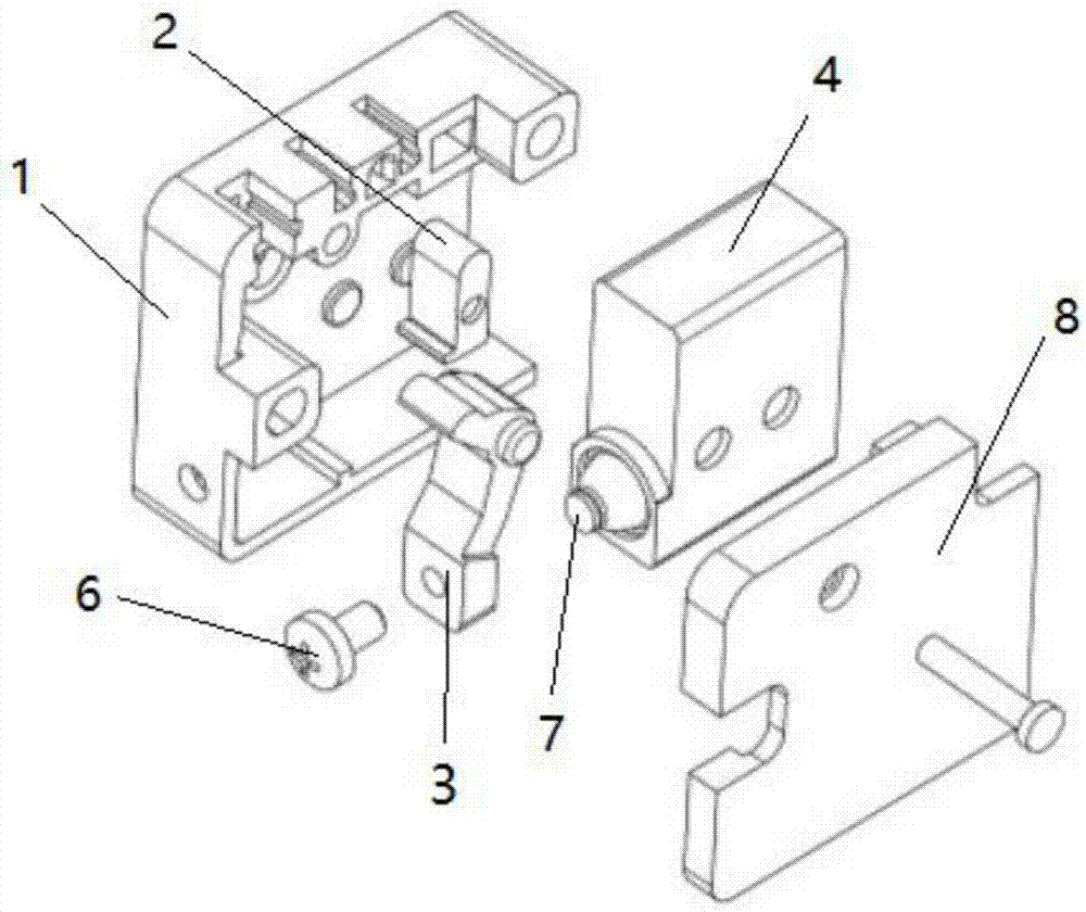
[0034] Such as Figure 1 to Figure 6 As shown, a lever-type micro-motion limit switch of the present invention includes a base 1, a button 2 arranged in the base 1, a connecting rod 3 and a limit switch 4, and the bending part of the connecting rod 3 is rotatably connected to the The base 1 and the root of the button 2 are connected to one end of the connecting rod 3. When the button 2 moves along its axial direction, one end of the connecting rod 3 is pressed to make it rotate around the bend, and the other end of the connecting rod 3 moves to touch the position of the limit switch 4. At the position of the movable rod 5, the end of the connecting rod 3 away from the button 2 is threadedly connected with an adjusting screw 6, the outer wall of the limit switch 4 is provided with a sealing cap 7 extend...


PUM


Abstract

The invention discloses a lever-type inching limit switch which includes a pedestal, and a button, a connecting pole and a limit switch which are arranged inside the pedestal. The bending position of the connecting pole is in rotary connection to the pedestal. The root part of the button is connected to one end of the connecting pole. When the button moves in the axial direction, one end of the connecting pole is pressed so as to rotate the bending position of the connecting pole, and the other end of the connecting pole moves and touches a movable pole of the limit switch. According to the invention, the lever-type inching limit switch, according to the level principle and the formula between angular velocity and linear velocity v=wr, when the button presses a shorter end of the connecting pole to move at a smaller velocity, the longer end of the connecting pole moves at a greater velocity, and if the greater velocity meets the requirements for minimum triggering velocity of the switch, the lever-type inching limit switch effectively prevents power disconnection when the switch acts or flickering of switch signals. The end parts of the connecting pole are provided with adjusting bolts of which the positions can be adjusted, so that operation range parameters of the button triggering the switch in an accurate manner and requirements for extremely small tolerance can be met.

Description

technical field [0001] The invention relates to a switch, in particular to a limit switch. Background technique [0002] The micro switch is a contact mechanism with a small contact interval and a quick-action mechanism, which performs switching actions with a specified stroke and a specified force. It is covered with a casing and has a trigger rod on the outside. Small, hence the name micro switch. The external mechanical force acts on the action reed through the transmission element (press pin, button, lever, roller, etc.). Click on or off quickly. When the force on the transmission element is removed, the action reed produces a reverse action force, and when the reverse stroke of the transmission element reaches the action critical point of the reed, the reverse action is completed instantaneously. The contact spacing of the micro switch is small, the action stroke is short, the pressing force is small, and the on-off is rapid. The action speed of its moving contact h...

Claims


Application Information

Patent Timeline
Patent Type & Authority Applications(China)
IPC IPC(8): H01H13/52H01H13/14H01H13/26
Inventor 戴四川
Owner ZHANGZHOU JUANMEI ELECTRIC TECH CO LTD
Why Eureka
Try Eureka