
Road Wheel Test Device with Elastic Damping Elements and Induced Tooth Curved Base

A technology of elastic damping and test equipment, which is applied in the field of vehicles, can solve the problems of unsuitable road wheels, large volume of driving drums of test benches, and no adjustment device for tires and drums, so as to reduce vibration and facilitate installation and adjustment Effect

Active Publication Date: 2019-05-24
CHINA NORTH VEHICLE RES INST
View PDF2 Cites 0 Cited by
  • Summary
  • Abstract
  • Description
  • Claims
  • Application Information

AI Technical Summary

Problems solved by technology

For example, the patent (CN203719922U) proposes a double-drum energy recovery tire friction and slip stiffness characteristic test device, but it can be seen from its test device that it is only suitable for ordinary car tires, not for road wheels
[0004] The contact distance between the road wheel and the driving drum needs to be adjusted by an adjustment mechanism. Although the patent (CN102401745A) proposes a road surface simulation device for the inner and outer drums with equal diameters, there is no device for adjusting the relative position between the tire and the drum.
[0005] The drum drive test bench of ordinary cars cannot meet the test requirements of special vehicle road wheels. Therefore, a test device that can meet the characteristics of the road wheels and meet the requirements of the test items is essential. Due to the size of the tested object-the road wheel diameter and width However, due to the large volume of the driving wheel drum of the test bench, it must be fixed. Therefore, an adjustment device is needed to adjust the relative position of the load wheel and the driving wheel drum, and the adjustment convenience and adjustment accuracy requirements must be considered at the same time. several aspects

Method used


Image

  • Road Wheel Test Device with Elastic Damping Elements and Induced Tooth Curved Base
  • Road Wheel Test Device with Elastic Damping Elements and Induced Tooth Curved Base
  • Road Wheel Test Device with Elastic Damping Elements and Induced Tooth Curved Base

Examples


Embodiment Construction

[0048]In order to make the purpose, content and advantages of the present invention clearer, the specific implementation manners of the present invention will be further described in detail below in conjunction with the accompanying drawings and embodiments.

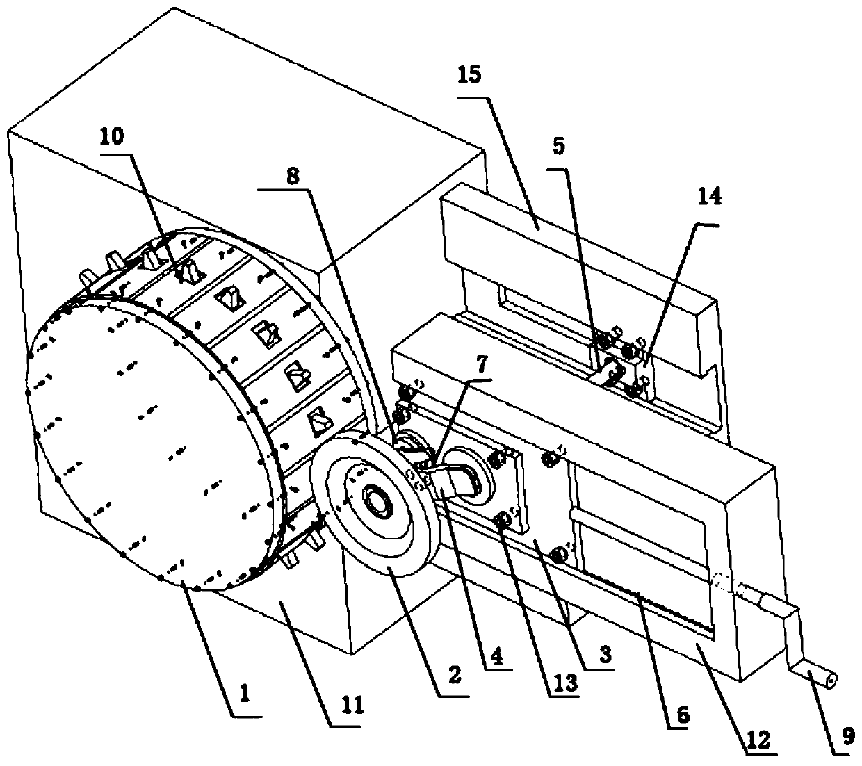
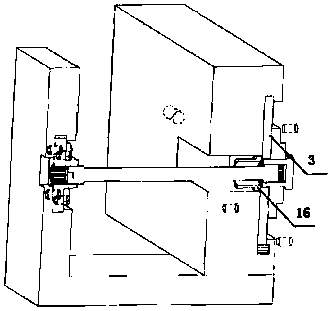
[0049] like figure 1 , figure 2 , image 3 and Figure 4 As shown, a load wheel test device with an elastic damping element and an arc-shaped base of induced teeth, including a driving drum 1, an arc-shaped base 10 with induced teeth, a rubber gasket 18, a fixed frame 11, a base 12, and a slide plate 3 , needle roller 6, lead screw propulsion mechanism 9, load wheel tested object 2, balance elbow 4, balance elbow seat 13, torsion bar spring 5, torsion bar spring seat 14, L-shaped base 15, rotary shock absorber 8. Connecting arm 7, angle sensor 16, motor 17, outer nut 23, inner nut 24, inner adjusting ring 25, outer adjusting ring 26, intermediate ring 27, bearing 28, etc.

[0050] Wherein, the motor 17 is installed ...


PUM


Abstract

The invention discloses a load wheel test device with an elastic damping element and an induction tooth arc base. The device comprises a fixed frame (11) and a load wheel component. A motor (17) is mounted on the fixed frame (11). The output shaft of the motor (17) is connected with a drive wheel hub (1). The motor (17) drives the drive wheel hub (1) to rotate. The drive wheel hub (1) is near one side of the fixed frame (11), and protrudes from the edge of the side. An arc base (10) with induction teeth is arranged on the circumferential surface of the drive wheel hub (1). The load wheel component includes a load wheel (2) mounted on one side of the surface of the drive wheel hub (1). With the device adopted, the characteristic, durability and other performances of the load wheel under a simulated actual condition can be tested. Rotary shock absorbers with different damping forces can be selected and used together with a torsion bar spring to simulate the dynamic force applied to a load wheel on an actual vehicle and to reduce the vibration during test.

Description

technical field [0001] The invention belongs to the field of vehicles and relates to a load wheel test device with an elastic damping element and an arc-shaped base of induced teeth. Background technique [0002] The road wheel is the supporting and moving part of the tracked vehicle. The connection between the road wheel and the car body is through a balance elbow, and a torsion bar spring and a rotary shock absorber are connected to the balance elbow. Since special vehicles are driven in harsh road conditions such as mountainous areas, the reliability of the durability of the road wheels is high. [0003] The road wheel is different from the rubber tire of ordinary cars. The structure of the road wheel uses a two-petal composite hub. The drum is bonded with a non-pneumatic rubber layer, which is in contact with the inner side of the track and does not directly contact the road. For example, the patent (CN203719922U) proposes a double-drum energy recovery tire friction and...

Claims


Application Information

Patent Timeline
Patent Type & Authority Patents(China)
IPC IPC(8): G01M17/013
CPCG01M17/013
Inventor 周宁宁龙振新范伟光药凌宇赵韬硕刘捷马国新
Owner CHINA NORTH VEHICLE RES INST
Learn More