
Fresnel photothermal concentrating structure and method based on non-imaging optical partition multi-focal

A technology of non-imaging optics and light-gathering structure, which is applied in the field of light-gathering, can solve the problems of the heat collector absorbing the deformation of the metal tube, reducing the light-gathering efficiency, deviating from the design position, etc., so as to improve the heat-gathering efficiency and reduce the thermal stress and deformation. , the effect of uniform heat flux density

Active Publication Date: 2019-09-24
HUAZHONG UNIV OF SCI & TECH
View PDF7 Cites 0 Cited by
  • Summary
  • Abstract
  • Description
  • Claims
  • Application Information

AI Technical Summary

Problems solved by technology

Therefore, from the perspective of safety, the deformation and bending of the metal tube will cause the rupture of the vacuum glass tube, causing safety problems, so the thermal stress and deformation caused by the temperature gradient cannot be ignored
From an economic point of view, under the working condition of non-uniform heat flux, the thermal stress will cause the collector to absorb metal tubes to deform, bend, and deviate from the design position, resulting in a significant drop in light concentration efficiency

Method used


Image

  • Fresnel photothermal concentrating structure and method based on non-imaging optical partition multi-focal
  • Fresnel photothermal concentrating structure and method based on non-imaging optical partition multi-focal
  • Fresnel photothermal concentrating structure and method based on non-imaging optical partition multi-focal

Examples


Embodiment Construction

[0035] In order to make the object, technical solution and advantages of the present invention clearer, the present invention will be further described in detail below in conjunction with the accompanying drawings and embodiments. It should be understood that the specific embodiments described here are only used to explain the present invention, not to limit the present invention. In addition, the technical features involved in the various embodiments of the present invention described below can be combined with each other as long as they do not constitute a conflict with each other.

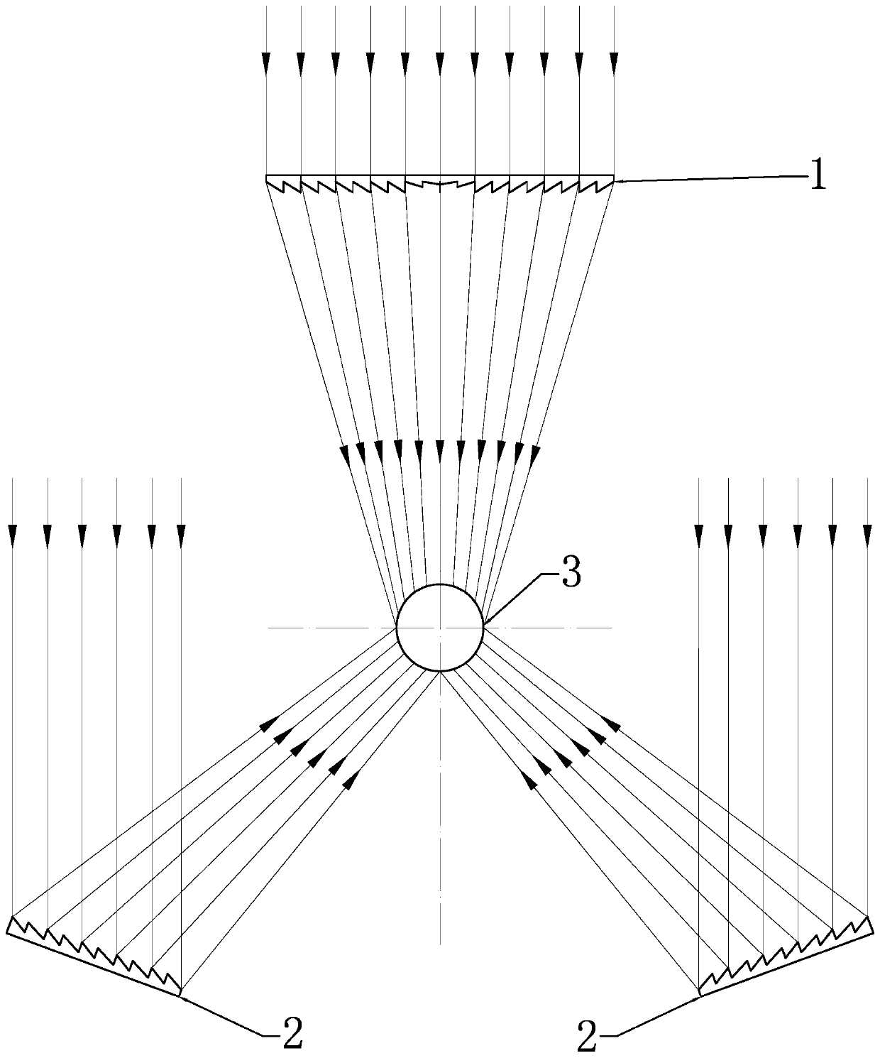
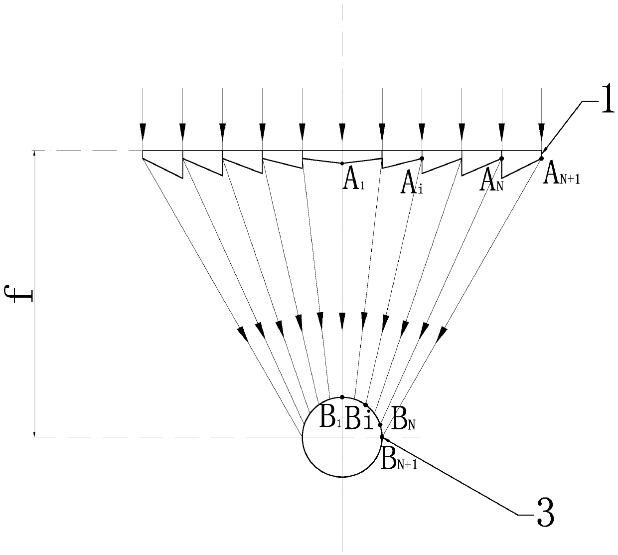
[0036] refer to Figure 1 to Figure 5 , based on non-imaging optical division multi-focal Fresnel photothermal concentrating structure, characterized in that it includes a Fresnel lens 1 and two linear Fresnel reflectors 2, wherein,

[0037] The Fresnel lens 1 and the two linear Fresnel reflectors 2 are used to cooperate together to heat the outer surface of the set area of ​​the heat collectin...


PUM


Abstract

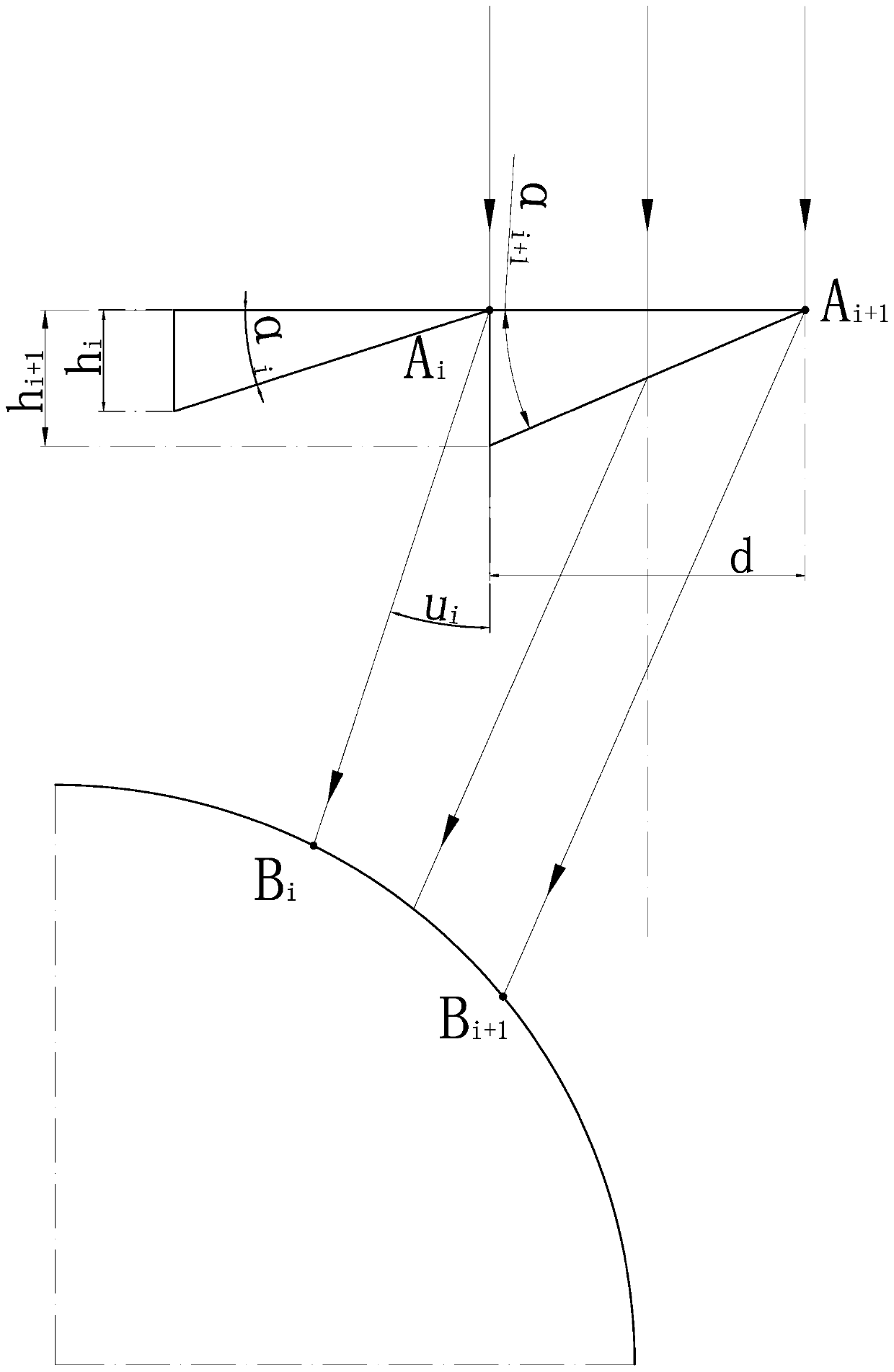
The invention belongs to the technical field of condensation and discloses an area-partitioning multi-focus Fresnel photo-thermal condensation structure and method based on the non-imaging optics. The area-partitioning multi-focus Fresnel photo-thermal condensation structure comprises a Fresnel lens and two linear Fresnel reflectors, wherein the Fresnel lens and the two linear Fresnel reflectors jointly cooperate to heat the outer surface of a set area of a heat collecting pipe. The area-partitioning multi-focus Fresnel photo-thermal condensation method comprises the steps of arranging the Fresnel lens and the two linear Fresnel reflectors, partitioning the area, partitioning focuses, conducting marginal light ray corresponding and designing the geometrical parameters of a Fresnel solar condensation device. According to the area-partitioning multi-focus Fresnel photo-thermal condensation structure, area partitioning and focus corresponding are conducted on an optical system and a heat collection target, light rays pass through the lens and the reflectors and can evenly reach the heat collection target, and therefore the surface thermal flux of the heat collection target are uniform; the thermal fluxes in all the partitioned areas are equal, when the number of the areas meets requirements, it can be guaranteed that the surface thermal flux of the whole vacuum heat collecting pipe is uniform, the thermal stress and deformation of the heat collecting pipe are reduced, and therefore the heat collection efficiency and the heating safety are improved.

Description

technical field [0001] The invention belongs to the field of light concentrating technology, and more specifically relates to a Fresnel photothermal light concentrating structure. Background technique [0002] Solar thermal power generation is to gather solar light through a concentrating device to obtain a high-temperature heat source, heat the working fluid, and obtain high-temperature and high-pressure steam to drive a turbogenerator to generate electricity. [0003] The Fresnel focusing device includes a Fresnel lens and a linear linear Fresnel reflector, which has outstanding advantages such as easy manufacture, low price, adjustable concentration ratio, low installation and fixing requirements, and easy maintenance. Therefore, the use of Fresnel-type solar concentrators is very popular in space applications and lighting, and extensive research work is being carried out through technological progress and feasibility of deployment in solar thermal power generation system...

Claims


Application Information

Patent Timeline
Patent Type & Authority Patents(China)
IPC IPC(8): F24S23/30F24S23/70F24S10/70F24S10/40
CPCF24S10/45F24S10/70F24S23/31Y02E10/44
Inventor 李建兰林鹏翥吴至易陈博
Owner HUAZHONG UNIV OF SCI & TECH
Learn More