
Elevator counterweight

A counterweight and component technology, applied in the field of assembly and counterweight, can solve problems such as difficulties and expensive modules, and achieve the effect of increasing volumetric efficiency, reducing height, and unaffected structural strength

Inactive Publication Date: 2017-08-04
KONE CORP
View PDF11 Cites 0 Cited by
  • Summary
  • Abstract
  • Description
  • Claims
  • Application Information

AI Technical Summary

Problems solved by technology

In the case of steel, these types of modules are expensive, whereas it is very difficult, if not impossible, to construct similar shape-locked modules from concrete

Method used


Image

  • Elevator counterweight
  • Elevator counterweight
  • Elevator counterweight

Examples


Embodiment Construction

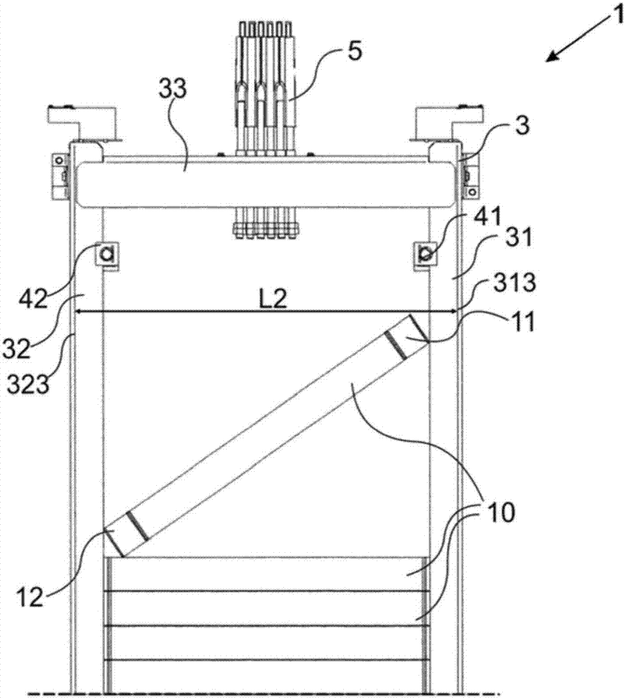
[0053] exist Figure 1a , Figure 2a , Figure 3a , Figure 4a and Figure 5a A counterweight 1 according to the invention is shown in . The counterweight comprises a frame 3 comprising a vertical first side beam 31 , a vertical second side beam 32 and two horizontal beams, of which only the upper top beam 33 is shown in all figures. It will be understood that the bottom beam is arranged between the two side beams 31 , 32 at the bottom of the frame 3 , extends horizontally between them and is aligned with the top beam 33 .

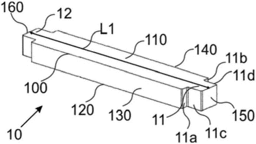
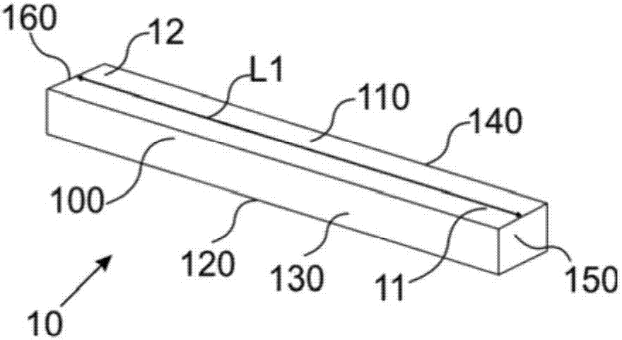
[0054] The frame 3 is filled with balancing modules 10 , 20 from the bottom beam upwards. Initially, the first modules 10 are used such that the first of the first modules 10 is positioned directly on top of the bottom beam, although the bottommost part of the bottom beam and counterweight 1 is not shown in the figure.

[0055] The counterweight 1 also comprises means 5 for attaching hoisting cables to the frame 3, and locking means 41, 42 for securin...


PUM


Abstract

The invention concerns a counterweight module, a locking element, a counterweight and a method for assembling a counterweight. The counterweight module (20) comprises a first part (20a) and a second part (20b), between which a straight joint (25) is arranged at right angle in relation to the longitudinal direction of the counterweight module (20). The counterweight locking element (28) can be used to secure the counterweight modules (20) into a counterweight frame (3). In the method, the counterweight (1) is filled with balancing modules (10, 20) starting from the bottom of the frame (3).

Description

technical field [0001] The invention relates to a counterweight module and a locking element for the counterweight module, a counterweight, and a method for assembling the counterweight. In particular, the counterweight module and locking element, the counterweight and the method for assembling the counterweight are intended for elevators. Background technique [0002] In traction elevators, counterweights are used to balance the load on the elevator car, thereby reducing the power required for the vertical movement of the elevator car. An elevator car and counterweight are attached to opposite ends of the hoisting ropes, and they reciprocate in the elevator hoistway. The movement of the counterweight is usually guided by at least one guide rail, usually two guide rails on two opposite sides of the counterweight. [0003] The counterweight is formed from a metal frame, usually consisting of two vertical side beams and two horizontal cross beams. The weight of the counterw...

Claims


Application Information

Patent Timeline
Patent Type & Authority Applications(China)
IPC IPC(8): B66B7/00B66B17/12
CPCB66B7/00B66B17/12
Inventor J·米科南M·拉萨南E·奥兰克J·穆斯塔拉蒂V·曼尼南J·赫基南J·科拉S·科文兰塔H·巴内曼
Owner KONE CORP
Learn More