
Feeding mechanism for assembling puncture type bare needle protection covers

A technology of feeding mechanism and protective cover, which is applied in the direction of conveyor objects, transportation and packaging, conveyor control devices, etc., can solve the problem that the falling position of the needle seat needle tube assembly and the protective cover cannot be aligned, the jig cannot move forward or There are deviations in the moving distance, and the protection cover cannot be reduced, so as to avoid movement, reduce defective products, and reduce cleaning work

Active Publication Date: 2017-08-04
江苏台正数控设备有限公司
View PDF13 Cites 3 Cited by
  • Summary
  • Abstract
  • Description
  • Claims
  • Application Information

AI Technical Summary

Problems solved by technology

However, in the current protective cover fastening device, the number of protective covers to be fastened in each batch is a fixed value, and it is impossible to reduce the number of protective covers to be fastened according to the number and position of defective products of the needle hub and needle tube assembly on the jig. The station where the unqualified needle seat and needle tube assembly has been eliminated on the tool still has the protective cover falling off, causing the redundant protective cover to be scattered on the work surface. The scattered protective cover is not only easy to lose, but also difficult to clean. If it falls on the transmission mechanism On the running track, it will also block the following jigs. The blocked jigs will not be able to move forward or have a deviation in the moving distance. All protective covers cannot fall on the corresponding needle seat and needle tube assembly, the assembly cannot continue, and manual shutdown must be performed for troubleshooting, which greatly reduces work efficiency and greatly increases defective products

Method used


Image

  • Feeding mechanism for assembling puncture type bare needle protection covers
  • Feeding mechanism for assembling puncture type bare needle protection covers
  • Feeding mechanism for assembling puncture type bare needle protection covers

Examples


Embodiment

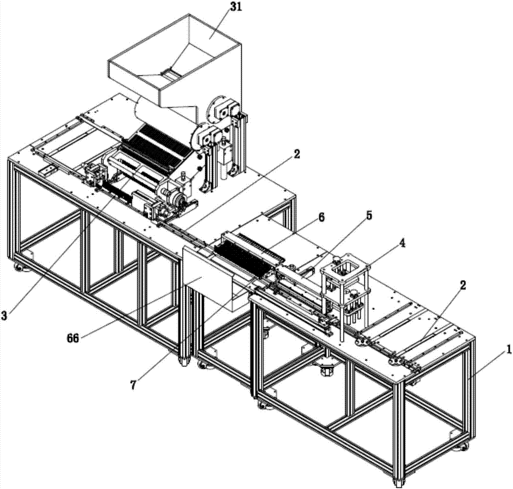
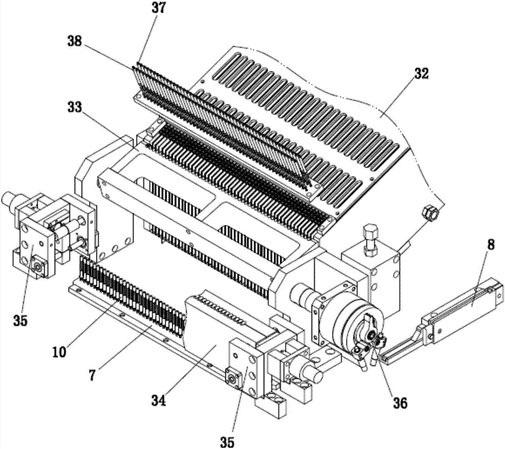
[0037] The specific embodiments of the present invention are as Figure 1 to Figure 8 As shown, a feeding mechanism for assembling a puncture-type bare needle protective cover includes a workbench 1, on which is provided a transmission mechanism 2 for moving a jig 7 carrying a needle holder needle tube assembly 9, and It includes an image comparison device 4, an air blocking detection device 5, a defective product discharge device 6 and a protective cover fastening device 3 arranged in sequence along the conveying direction of the transmission mechanism 2. The protective cover fastening device 3 can only buckle the protective cover The structure that fits the remaining needle holder needle tube assembly 9 on the jig 7. In this embodiment, the transmission mechanism 2 is a conveyor belt, and the jig 7 is provided with 50 vertical positioning posts.

[0038] After the needle holder and needle tube assembly 9 on the jig 7 are glued to each other and enter the adhesive curing oven, ...


PUM


Abstract

The invention discloses a feeding mechanism for assembling puncture type bare needle protection covers. The feeding mechanism comprises a workbench. A conveying mechanism used for moving a jig carrying needle seat and needle tube assemblies is arranged on the workbench. The feeding mechanism further comprises an image comparison device, an air blockage detection device, a defective product discharging device and a protection cover buckling device which are sequentially arranged in the conveying direction of the conveying mechanism. The protection cover buckling device is of a structure which can only buckle the protection covers on the residual needle seat and needle tube assemblies on the jig. According to the feeding mechanism for assembling the puncture type bare needle protection covers, the situation that jig movement is stopped due to the fact that the redundant protection covers fall onto the workbench is avoided, normal buckling of the protection covers of the needle seat and needle tube assemblies on the jig is guaranteed, work efficiency is improved, and defective products are greatly reduced.

Description

Technical field [0001] The present invention relates to the field of assembling medical equipment, in particular to a feeding mechanism for assembling a puncture-type bare needle protective cover. Background technique [0002] In the current automatic assembling device for medical devices with needle tube puncture type, the transfer jig is first placed in the transmission mechanism, and the jig is moved to different positions through the transmission mechanism. A plurality of positioning posts are arranged in a straight line on the jig, the needle tube of the assembled needle holder needle tube assembly faces upward, and the hole at the bottom of the needle holder is sleeved on the positioning post of the jig, thereby fixing the needle holder needle tube assembly on the jig. After the needle holder and needle tube components on the jig are glued to each other and enter the adhesive curing oven, the sharpness of the needle and the coating amount of the adhesive need to be checked ...

Claims


Application Information

Patent Timeline
Patent Type & Authority Applications(China)
IPC IPC(8): B23P19/00B65G43/08B65G47/90
CPCB65G43/08B65G47/901B23P19/001
Inventor 王琳
Owner 江苏台正数控设备有限公司
Learn More