An air blower

A blower and air supply technology, which can be applied to mechanical equipment, machines/engines, liquid fuel engines, etc., and can solve problems such as inconvenience in use

Inactive Publication Date: 2017-07-28
TWINBIRD CORP
View PDF3 Cites 2 Cited by
  • Summary
  • Abstract
  • Description
  • Claims
  • Application Information

AI Technical Summary

Problems solved by technology

[0010] In the above-mentioned portable blower, the air sucked in from the suction port is blown out by the fan. Therefore, similar to the above-mentioned knapsack blower and the portable blower, there is the following problem: if the sucked air contains dust, sand, etc., Air containing dust, sand, etc. is ejected
[0011] In addition, in the above-mentioned portable blower, the air outlet is provided on the front upper part of the main body part, and the suction port is provided at the center part of the left side of the main body part in a different position and

Method used


Image

  • An air blower
  • An air blower
  • An air blower

Examples


Embodiment 1

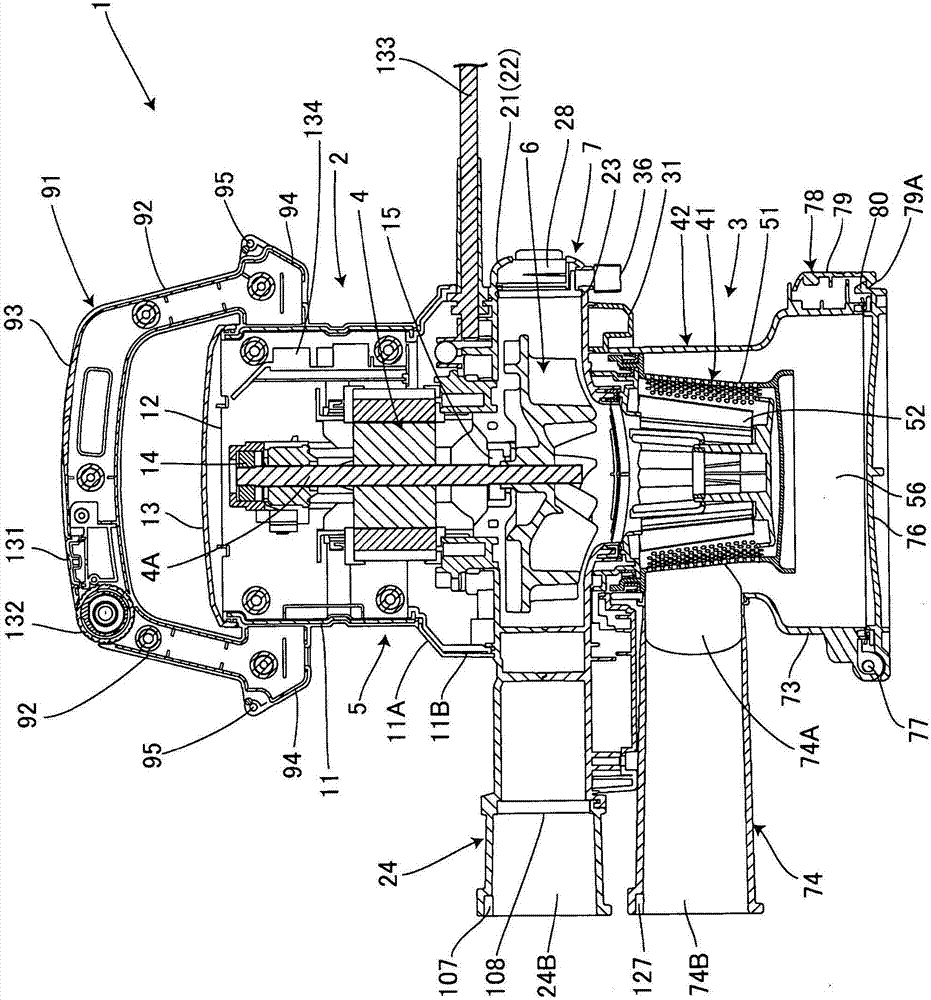
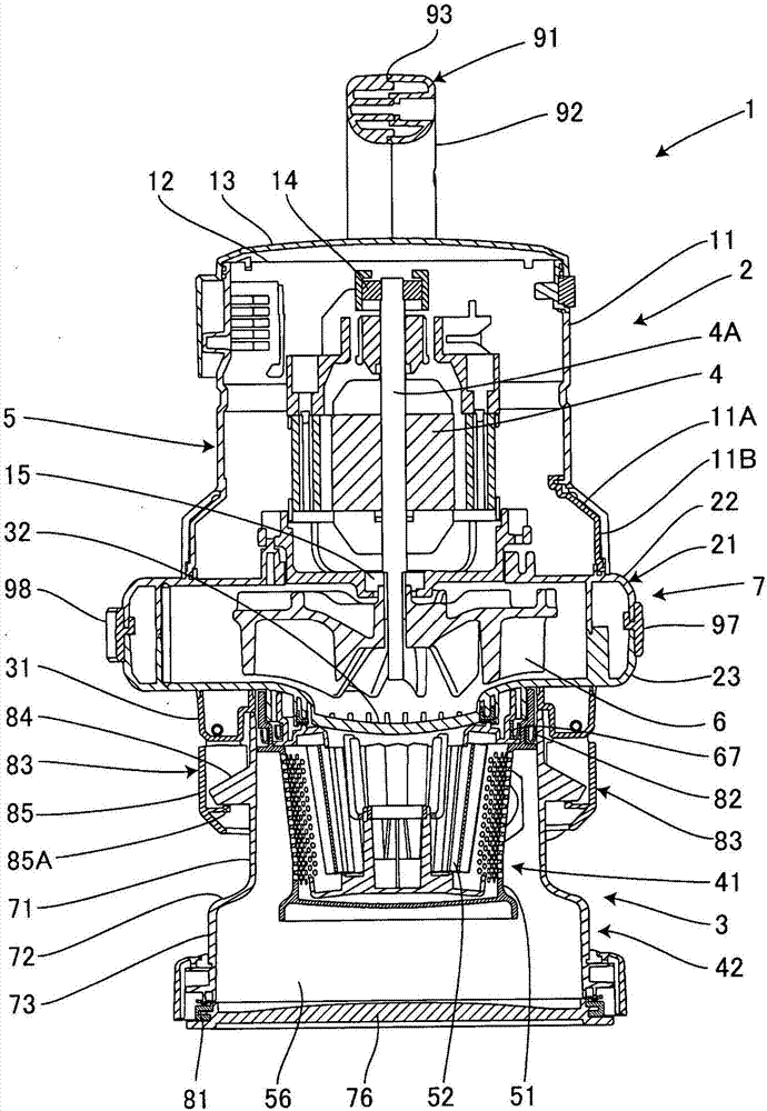
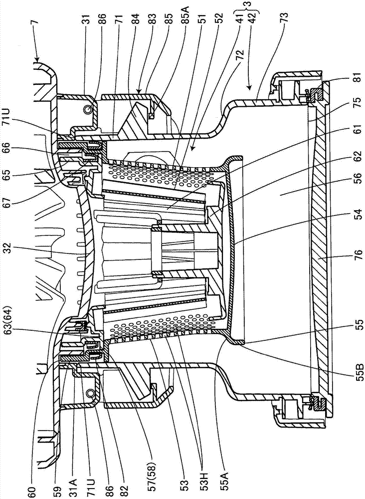
[0063] Below, based on Figure 1 to Figure 12 Example 1 of the present invention will be described. Reference numeral 1 is the blower of the present invention. This blower 1 has a main body 2 and a dust removal part 3 detachably attached to the lower part of this main body 2 . In addition, the main body 2 has a main body part 5 and a blower part 7, the main part 5 has a built-in motor 4, and the blower part 7 is arranged at the bottom of the main part 5 and has a centrifugal fan 6 built in. The dust removal unit 3 is detachably attached to the lower portion of the wind unit 7 .

[0064] A cylindrical main body case 11 is provided on the outside of the main body 5, and an enlarged portion 11A extending downward and conically expanding is provided on the lower side of the main body case 11. The enlarged portion 11A is The lower main body case lower portion 11B is formed to have a larger diameter than the upper portion. In addition, the upper opening 12 of the main body case ...

Embodiment 2

[0120] Figure 13 as well as Figure 14 Embodiment 2 of the present invention is shown, and the same parts as those in the above-mentioned Embodiment 1 are given the same reference numerals, and the explanation thereof will be omitted, and will be described in detail. Figure 13 as well as Figure 14 A modified example of the mounting positions of the discharge port 24 and the air intake port 74 is shown.

[0121] Such as Figure 13 as well as Figure 14As shown, in this example, the suction port 74 is protrudingly provided at the lower part of the air blower housing 21 of the main body 2 on the left side, and in addition, on the right side of the air blower housing 21 The discharge port 24 is provided, and the suction port 74 and the discharge port 24 are parallel to each other and face forward.

[0122] In addition, a dust box side connecting hole 136 is formed on the upper left side of the dust collecting box 42 , and an air inlet side connecting hole 137 connected to ...


PUM


Abstract

The present invention provides an air blower through which ejected air is free of dust and the like. The air blower (1) is provided with a main body (2) and a dedusting part (3). The main body comprises a main part (5) and a scroll air supplying part (7). A motor (4) is disposed in the main part. A centrifugal fan (6) is in-built in the air supplying part and a cylindrical ejecting port (24) is formed in the air supplying part. The dedusting part can be mounted on the main body in a removable manner. The main body and the dedusting part are arranged in an up-down manner. The dedusting part is mounted at the upstream side of the centrifugal fan. The motor is disposed in the main body in a manner that the rotating axis (4A) of the motor is longitudinal, and the ejecting port protrudes transversely from the periphery of the air supplying part, and therefore dust in the dedusting part at the upstream side of the centrifugal fan is removed, dedusted air is ejected from the ejecting port, and the ejecting position is not contaminated by dust or the like. The rotating axis of the motor is longitudinally arranged so that the overall air blower is longitudinally long, can be hung on shoulders through shoulder belts and can be easily used.

Description

technical field [0001] The present invention relates to a blower with a discharge port. Background technique [0002] Conventionally, as such blowers, the following knapsack blowers (for example, Patent Document 1), portable blowers (for example, Patent Document 2), and the like have been proposed. The knapsack blower has a back frame and a blower unit. The back frame has a back plate arranged along the back of the operator and a base portion extending rearward from the lower end of the back plate. The blower unit is The rear side of the back plate portion of the backpack frame is mounted on the base portion, and the fan, which is rotatably supported in the volute around the axis in the front-rear direction, is rotated by the power machine to blow out the air sucked from the suction opening. The volute has the suction opening for taking in external air at the front side. The portable blower has: a motor housing, the motor housing is built in the motor and protrudes to one ...

Claims


Application Information

Patent Timeline
IPC IPC(8): F04D29/70F04D29/42
CPCF04D29/4206F04D29/4213F04D29/703
Inventor 反町干夫
Owner TWINBIRD CORP
Why Eureka
Try Eureka