Oil pollution separation device for sludge

An oil pollution separation and equipment technology, applied in water/sewage treatment equipment, water/sludge/sewage treatment, sludge treatment, etc., can solve problems such as high cost, improve air quality, low production cost, and good treatment effect Effect

Pending Publication Date: 2017-07-28
ANHI SHENGYUN HEAVY MACHINERY CO LTD
View PDF6 Cites 0 Cited by
  • Summary
  • Abstract
  • Description
  • Claims
  • Application Information

AI Technical Summary

Problems solved by technology

Although this treatment method is convenient, it will produce some chemical pollution more or less, and it also has a higher cost.

Method used


Image

  • Oil pollution separation device for sludge
  • Oil pollution separation device for sludge
  • Oil pollution separation device for sludge

Examples


Embodiment Construction

[0023] In order to make the purpose, technical solutions and beneficial effects of the present invention more clear, the preferred embodiments of the present invention will be described in detail below in conjunction with the accompanying drawings, and the present invention will be further described to facilitate the understanding of technical personnel.

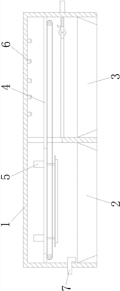
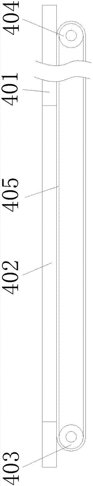
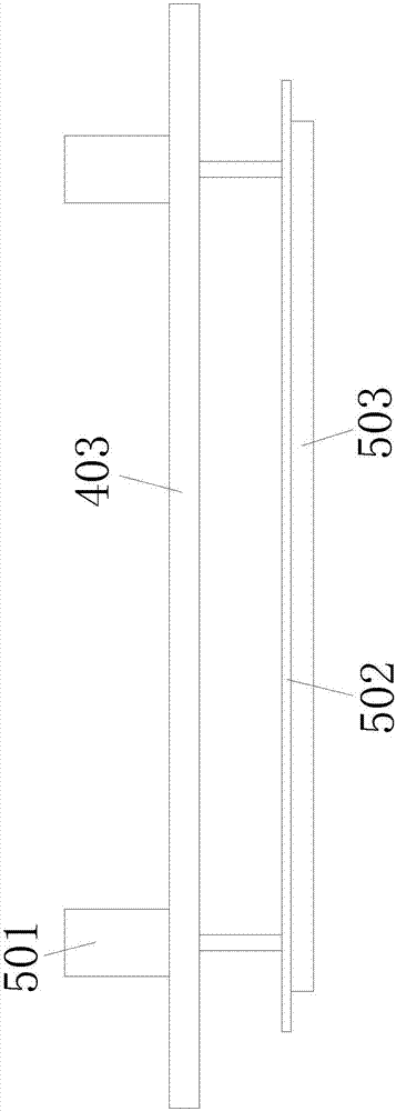
[0024] Such as Figure 1 to Figure 4 As shown, a sludge oil separation equipment includes a housing 1, a storage tank 2, an oil storage tank 3, a transmission device 4, a suction device 5, and a liquid discharge device 6. The storage tank 2 is installed in the housing 1, the oil storage tank 3 is installed on the right part of the housing 1, the transmission device 4 is installed on the upper part of the housing 1, the suction device 5 is installed on the transmission device 4, and the liquid discharge device 6 is installed above the oil storage tank 3. When in use, the sludge is placed in the storage tank 2, the oil storag...


PUM


Abstract

The invention discloses an oil pollution separation device for sludge. The oil pollution separation device comprises a shell, a material storage tank, a oil storage tank, a transmission device, a suction device and a liquid discharging device, the material storage tank is mounted on the left side of the shell, the oil storage tank is mounted on the right side of the shell, the transmission device is mounted on the upper portion of the shell, the suction device is mounted on the transmission device, and the liquid discharging device is mounted above the oil storage tank. An oil pollution layer on the upper portion of the sludge can be rapidly separated, the oil pollution separation device has good treatment effect and low production cost, air pollution can be effectively avoided by the aid of a closed shell structure, and the air quality of an operation space is improved.

Description

technical field [0001] The invention relates to the technical field of oily dirt separation equipment for sludge, in particular to an oily dirt separation equipment for sludge. Background technique [0002] Sludge is a solid sedimentary substance produced in the process of water and sewage treatment. It is a complex heterogeneous body composed of organic debris, bacterial cells, and inorganic particles. In the sludge treatment process, the oil in the sludge needs to be recovered, but currently it is basically recovered through chemical treatment. Although this treatment method is convenient, it will produce some chemical pollution more or less, and it also has a higher cost. Therefore, there is a need in the market for a physical device that has low production cost, is easy to use, and can carry out initial oil pollution treatment of sludge. Contents of the invention [0003] In order to solve the above technical problems, the present invention provides an oily dirt sepa...

Claims


Application Information

Patent Timeline
Patent Type & Authority Applications(China)
IPC IPC(8): C02F11/12
CPCC02F11/121C02F2201/002
Inventor 汪玉徐方应
Owner ANHI SHENGYUN HEAVY MACHINERY CO LTD
Why Eureka
Try Eureka