Eureka AIR delivers breakthrough ideas for toughest innovation challenges, trusted by R&D personnel around the world.

Liquid crystal display

A technology of liquid crystal display device and liquid crystal box, which is applied in nonlinear optics, instrumentation, optics, etc., and can solve problems such as color crosstalk, color crosstalk between different pixels, backlight light emitting angle, large quantum dot liquid crystal panel, etc.

Inactive Publication Date: 2017-07-25
HISENSE VISUAL TECH CO LTD
View PDF0 Cites 16 Cited by
  • Summary
  • Abstract
  • Description
  • Claims
  • Application Information

AI Technical Summary

Problems solved by technology

However, in the prior art, due to the large angle of light output from the backlight, the problem of color crosstalk between different pixels in the quantum dot liquid crystal panel often occurs.
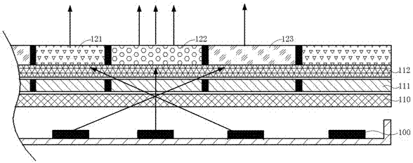
[0004] For color crosstalk between pixels, please refer to Figure 1a As shown, taking the display of green pixels as an example, the liquid crystal cell 111 corresponding to the green pixel unit 122 is in the open state, and the liquid crystal cell 111 corresponding to the red pixel unit 121 and the blue pixel unit 123 is in the closed state, but the backlight provided by the backlight source 100 The light output angle is relatively large. After the blue backlight is processed by the lower polarizer 110, the liquid crystal cell 111 and the upper polarizer 112, it can still irradiate the red pixel unit 121 and the blue pixel unit 123. The red pixel unit 121 has quantum dot materials. After receiving the blue backlight, red light is emitted; when the blue backlight passes through the blue pixel unit 123, it is directly transmitted, so that when displaying green, red light and blue light are generated, thereby reducing the color purity of the green light
Similarly, red pixels and blue pixels also have the problem of color crosstalk

Method used


Image

  • Liquid crystal display
  • Liquid crystal display
  • Liquid crystal display

Examples


Embodiment 1

[0044] Embodiment 1 of the present application provides a liquid crystal display device. Such as Figure 2a As shown, the display device includes a liquid crystal panel 500 and a backlight module 400 for providing backlight. The liquid crystal panel 500 is opposite to the backlight module 400 , and the liquid crystal panel 500 is disposed above the backlight module 400 .

[0045]The liquid crystal panel 500 includes a quantum dot color pixel layer 520, an upper polarizer 512, a liquid crystal cell 511, and a lower polarizer 510 stacked in sequence. The quantum dot color pixel layer 520 includes a plurality of red pixel units 521, a plurality of green pixel units 522 and A plurality of blue pixel units 523, wherein the red pixel unit 521 is provided with red quantum dot material, the green pixel unit 522 is provided with green quantum dot material, and the blue pixel unit 523 is not provided with quantum dot material. After the blue backlight is processed by the lower polarize...

Embodiment 2

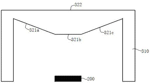
[0066] The light emitting surface of the light-emitting device used to provide backlight in the liquid crystal display device described in Embodiment 1 is a plane. The purpose of this embodiment is to provide another light-emitting device used for backlight. For the specific structure, please refer to Figure 3a As shown, the light emitting device includes an LED light source 200 and a light collimating structure 300 , and the LED light source 200 is disposed below the light collimating structure 300 . Wherein, the light collimation structure 300 includes a support frame 310 and a collimator 320 arranged between the support frames, the collimator includes a light incident surface 321 and a light exit surface 322, and the light incident surface 321 and the light exit surface 322 are respectively circumferentially symmetrical, In addition, the derivation process of the conditions satisfied by the structure of the light-incident surface 321 of the light-emitting device provided in...


PUM


Abstract

The application of the invention provides a liquid crystal display, comprising a liquid crystal panel that comprises a quantum dot color pixel layer, an upper polarizer, a liquid crystal box and a lower polarizer stacked in sequence; the quantum dot color pixel layer comprises red pixel unis, green pixel units and blue pixel units. The liquid crystal display also comprises a backlight module arranged below the liquid crystal panel, the backlight module comprises a back plate and a light-emitting device arranged on the back plate, and the light-emitting device comprises an LED light source and a light collimating structure arranged above the LED light source. According to Lagrange invariant, the light collimating structure is arranged above the LED light source, light outgoing aperture is enlarged, emergent angle of backlight is decreased, the light emerges under certain degree of collimation, and therefore, the problem that large backlight emergence angle of the liquid crystal panel during image displaying leads to inter-pixel color crosstalk is solved.

Description

technical field [0001] The invention relates to the field of display technology, in particular to a liquid crystal display device. Background technique [0002] At present, a new display method of LCD TV is to directly replace the color filter in the traditional liquid crystal panel with the quantum dot color pixel layer, which mainly includes red pixel unit, green pixel unit and blue pixel unit, wherein the red pixel unit is set to red Quantum dot material; green pixel unit is set with green quantum dot material; blue pixel unit is not set with quantum dot material. When the blue backlight shines on the red, green and blue pixel units, the blue backlight in the blue pixel unit directly transmits and emits blue light; the quantum dot material in the green pixel unit absorbs blue light and converts it into green light, and the red pixel unit The quantum dot material absorbs blue light and converts it into red light. [0003] Since the quantum dot material will change the ph...

Claims


Application Information

Patent Timeline
Patent Type & Authority Applications(China)
IPC IPC(8): G02F1/13357
CPCG02F1/133603G02F1/133606G02F1/133614
Inventor 李富琳宋志成刘卫东
Owner HISENSE VISUAL TECH CO LTD
Why Eureka
Eureka Blog
Learn More