Condensate water collection device with rotary impeller

A collection device and rotating impeller technology, applied in air heaters, lighting and heating equipment, fluid heaters, etc., can solve the problems of slow flow of condensed water, threats to user safety, exhaust of smoke into the room, etc., and achieve the goal of reducing blockage Possibility, optimization of internal flow channel structure, and enhanced flow effect

Pending Publication Date: 2017-07-25
GUANGDONG MACRO GAS APPLIANCE
View PDF8 Cites 2 Cited by
  • Summary
  • Abstract
  • Description
  • Claims
  • Application Information

AI Technical Summary

Problems solved by technology

[0003] 1. At present, all condensed water collection devices use direct discharge or overflow to discharge condensed water. Since the generated condensed water has a slow flow rate and contains a small amount of impurities in the condensed water, the condensed water is often not discharged smoothly, and it is used for a long time. clogging may occur after
[0004] 2. At present, many condensed water collection devices discharge condensed water through direct discharge, causing the smoke to be discharged into the room along with the condensed water, threatening the safety of users

Method used


Image

  • Condensate water collection device with rotary impeller
  • Condensate water collection device with rotary impeller

Examples


Embodiment Construction

[0015] Below in conjunction with accompanying drawing and embodiment the patent of the present invention will be further described.

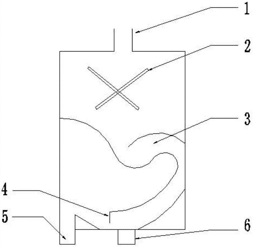
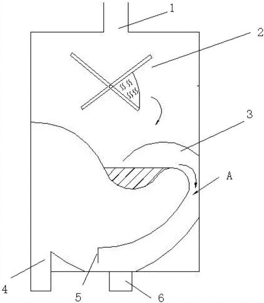
[0016] Such as figure 1 , figure 2 As shown, the heating device of the present invention, such as the condensed water collecting device of the gas water heater, comprises the inlet 1 of the condensed water collecting device on the upper part, the water storage rotating impeller 3 below the inlet 1 of the condensed water collecting device, and its center is the center of the water inlet 1 Offset by about 3-5mm, the middle internal condensed water collection channel and the lower condensed water collection device drain 6, the internal flow channel is an inverted S-shaped siphon structure channel 3, using the siphon principle to strengthen The flow of condensed water enables the condensed water to be collected and discharged reasonably. The top of the device is the inlet 1 of the condensate collection device, and a water seal baffle 4 is added a...


PUM


Abstract

The invention discloses a condensate water collection device with a rotary impeller. The condensation water collection device comprises a collection flow channel for condensate water collection. The condensate water collection device is characterized in that the interior flow channel is of a reversed-S-shaped siphon structure, and the water storage rotary impeller is arranged below an inlet of the condensate water collection device. A water seal baffle is additionally arranged at the tail end of the flow channel, and condensate water forms water seal at the tail end of the flow channel when drained. The condensate water collection device can effectively prevent smoke from being exhausted to a room along with the condensate water, enhance flowing of the condensate water, enable the condensate water to be reasonably collected and drained and reduce the possibility of blockage.

Description

technical field [0001] The invention relates to the technical field of condensed water collection, in particular to the technical field of condensed water collection devices for heating devices such as gas water heaters. Background technique [0002] There are two major disadvantages in the use of existing heat-burning devices such as condensed water collection devices for gas water heaters: [0003] 1. At present, all condensed water collection devices use direct discharge or overflow to discharge condensed water. Since the generated condensed water has a slow flow rate and contains a small amount of impurities in the condensed water, the condensed water is often not discharged smoothly, and it is used for a long time. A blockage may occur afterwards. [0004] 2. At present, many condensed water collection devices discharge condensed water through direct discharge, causing the smoke to be discharged into the room along with the condensed water, threatening the safety of us...

Claims


Application Information

Patent Timeline
IPC IPC(8): F24H8/00F24H9/16
CPCF24H8/006F24H9/16Y02B30/00
Inventor 余少言刘兵李冲刘晓东
Owner GUANGDONG MACRO GAS APPLIANCE
Why Eureka
Try Eureka