
Granular bed filtering dust removal system

A particle bed filtration and dust removal system technology, which is applied in the direction of dispersed particle separation, separation methods, chemical instruments and methods, etc., can solve the problems that affect the settlement and discharge of fine dust, the difficulty of preventing tar and dust accumulation, and the inability to accept back blowing gas, etc. , to achieve the effect of promoting dust settlement, stable work with little impact, and efficient and reliable removal

Active Publication Date: 2017-07-25
NINGBO UNIV
View PDF16 Cites 1 Cited by
  • Summary
  • Abstract
  • Description
  • Claims
  • Application Information

AI Technical Summary

Problems solved by technology

[0004] But, there is following problem in above-mentioned granule bed filter deduster in implementation process: because the granule layer in an inner housing back-blowing gas flow rate is 1.5~ of the average filter gas flow rate of the granule layer in this inner housing 2.5 times, so the blowback gas of the particle layer in the inner shell of the lowest second layer cannot be accepted by the particle layer in the inner shell of the lowest first layer, which will cause the blowback gas to carry the dust upwards, and the particles The blowback gas of the particle layer in the inner casing of the lowest first layer of the bed filter dust collector can only flow upwards, causing the fine dust to swirl between the lowest first layer to the lowest third layer, affecting the fine dust settlement and discharge
In order to make the blowback gas flow downward, although a circulating fan can be used to extract air from the lower part of the particle bed filter dust collector to force the backwash gas and dust to be drawn from the lower part and circulate back to the dusty gas inlet of the particle bed filter dust collector, but when When the temperature is high and the dust hardness is high, the blades in the circulating fan will wear seriously, especially when the gas contains a lot of tar, the anti-tar and dust accumulation in the circulating fan is a problem

Method used


Image

  • Granular bed filtering dust removal system
  • Granular bed filtering dust removal system
  • Granular bed filtering dust removal system

Examples


Embodiment 1

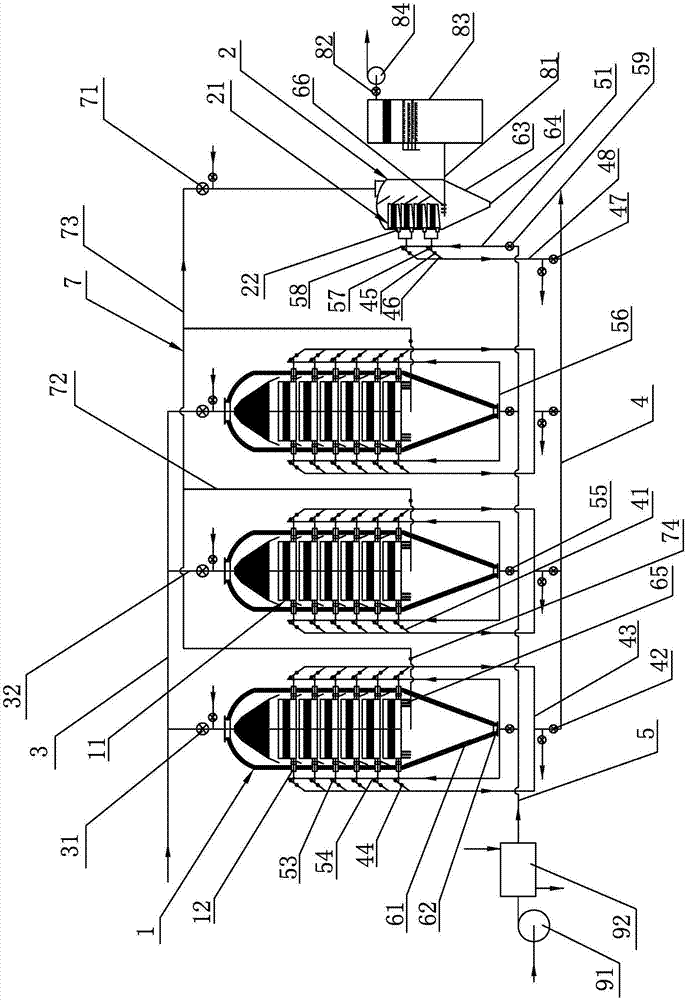
[0031] A kind of particle bed filter dust removal system that present embodiment proposes, such as figure 1 As shown, it includes three main particle bed filter dust collectors 1, a secondary particle bed filter dust collector 2, dusty gas main pipe 3, clean gas main pipe 4 and back blowing gas main pipe 5, and a main particle bed filter dust collector 1 There are six layers, two in each layer, and a total of twelve primary particle beds 11. The top of the primary particle bed filter and dust collector 1 is connected to the dust-containing gas main pipe 3, specifically, the dust-containing gas main pipe 3 is connected in series with the main dust-containing gas main pipe 3. The main dust-containing air inlet branch pipe 32 of the intake valve 31 is connected with the top of the main particle bed filter dust collector 1, and the dust-containing gas main pipe 3 transports the dust-containing gas to the main particle bed filter dust collector 1, and the main particle bed filter du...

Embodiment 2

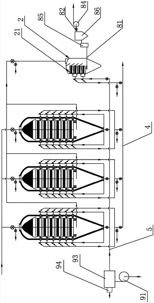
[0040] A kind of particle bed filter dust removal system that present embodiment proposes, such as figure 2 As shown, it is basically the same structure as the particle bed filter and dust removal system of Embodiment 1, the difference is only: the upstream of the reverse blowing air main pipe 5 is connected with a reverse blower 91, and the inlet end of the reverse blower 91 feeds clean gas. During processing, the inlet end of the reverse blower 91 communicates with the outlet end of the external clean air induced draft fan (not shown) or communicates with the external clean air gas cabinet to feed clean air, and the outlet end of the reverse blower 91 connects with the reverse blow air main pipe A mixer 93 for mixing clean gas and high-temperature flue gas is provided between the inlet ends of the gas inlet 5, and the mixer 93 is connected to a burner 94 that provides high-temperature flue gas, and the low-temperature clean gas is raised to back blowing by mixing high-temper...

Embodiment 3

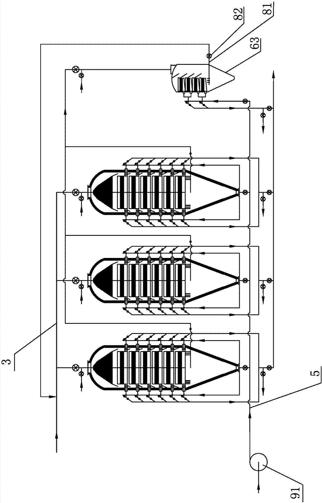
[0043] A kind of particle bed filter dust removal system that present embodiment proposes, such as image 3 As shown, it is basically the same as the structure of the particle bed filter and dust removal system of embodiment one or the structure of the particle bed filter and dust removal system of embodiment two, the only difference is: the upstream of the back blowing air main pipe 5 is connected with a reverse blower 91, The inlet end of the reverse blower 91 is fed with high-temperature flue gas. In actual processing, the inlet end of the reverse blower 91 is connected with the high-temperature flue gas pipeline (not shown in the figure), and the high-temperature flue gas is directly introduced to meet the temperature requirements of the reverse blower. The high-temperature flue gas is used as the blowback gas. The outlet end of the dust-laden back-blowing gas outlet pipe 81 is connected in series with the outlet valve 82 and connected to the dust-laden gas main pipe 3. Wh...


PUM


Abstract

The invention discloses a granular bed filtering dust removal system. The granular bed filtering dust removal system comprises at least one main granular bed filtering dust collector and a secondary granular bed filtering dust collector, a dust-containing air main pipe, a clean air main pipe and a blowback air main pipe, wherein the dust-containing air main pipe conveys dust-containing air into the main granular bed filtering dust collector, the clean air main pipe outputs clean air filtered by the main granular bed filtering dust collector, the bottom of the main granular bed filtering dust collector is provided with a main ash hopper, the blowback air main pipe conveys blowback air into the main granular bed filtering dust collector, the secondary granular bed filtering dust collector is provided with a dust-containing air introduction pipe used forcommunicating the secondary granular bed filtering dust collector with the upper portion of the main ash hopper, the dust-containing air introduction pipe conveys powder-containing air into the secondary granular bed filtering dust collector, the clean air main pipe outputs clean air filtered by the secondary granular bed filtering dust collector, the blowback air main pipe conveys blowback air into the secondary granular bed filtering dust collector, and the bottom of the secondary granular bed filtering dust collector is provided with a secondary ash hopper. The granular bed filtering dust removal system has the advantage that the fine dust that is difficult to settle can be efficiently and reliably removed.

Description

technical field [0001] The invention relates to a filter and dust removal system, in particular to a particle bed filter and dust removal system. Background technique [0002] The particle bed filter dust removal system has unique advantages in the field of high temperature gas dust removal. [0003] For example, the invention patent "a granular bed filter dust collector" announced by China (the application date is January 31, 2007, the announcement number is CN101036846A, and the patent number is ZL200710067109.7), which includes an outer shell and a shell set along the height direction There is at least one layer of filtering device in the body. The upper part of the outer casing is provided with a dust-containing gas inlet, and the lower end of the outer casing is provided with a dust outlet. The filtering device is equipped with an independent gas reversing device, which is connected to a clean gas main pipe and The back blowing air main pipe is characterized in that th...

Claims


Application Information

Patent Timeline
Patent Type & Authority Applications(China)
IPC IPC(8): B01D50/00
CPCB01D50/20
Inventor 杨国华
Owner NINGBO UNIV
Learn More