Stereoscopic rotary feeding device

A feeding device, three-dimensional technology, applied in conveyor control device, stacking, transportation and packaging of objects, etc., can solve the problem of unutilized space, large area, and the inability to implement the project plan of the production line occupied by the feeding device, etc. problems, to achieve the effect of saving workplace area, reducing feeding frequency, reducing labor intensity and assisting feeding time

Pending Publication Date: 2017-07-21
无锡津九合盛机床有限公司
View PDF5 Cites 3 Cited by
  • Summary
  • Abstract
  • Description
  • Claims
  • Application Information

AI Technical Summary

Problems solved by technology

[0003] With the continuous development of the enterprise, there are more and more mechanical equipment without increasing the area of ​​the plant, and the effective working area in the plant is becoming more and more tight. Therefore, the area occupied by the feeding device of the automatic production line is very important for the entire production line. Often, the entire production line project plan cannot be implemented because the land occupation problem of the feeding device cannot be solved
[0004] At present, most of the general automatic production lines adopt the method of horizontal layout, chain or belt conveying, and manual work site supplementary feeding, which requires a large area, especially the feeding device, which cannot use the space

Method used


Image

  • Stereoscopic rotary feeding device
  • Stereoscopic rotary feeding device
  • Stereoscopic rotary feeding device

Examples


Embodiment Construction

[0027] The present invention will be further described below in conjunction with accompanying drawing:

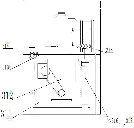
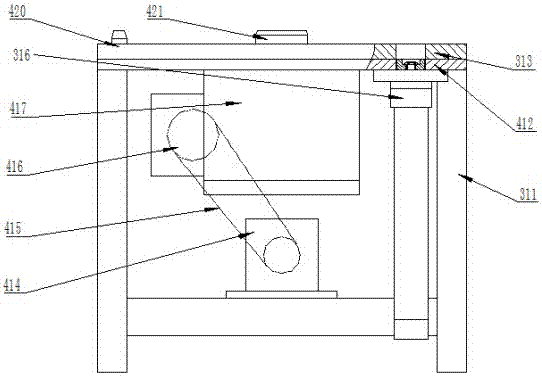
[0028] Such as figure 1 , figure 2 and Figure 4 As shown in the three-dimensional rotary feeding device, the rotary platform 313 is installed on the rotary platform 412 of the rotary platform bracket 311, the rotary platform 313 is connected to the rotary platform driving part 312, and the rotary platform 313 is driven by the rotary platform driving part 312 to rotate around the center, and the parts are rotated around the center. The turntable 314 is installed on the turntable 313 through the positioning shaft 421, and rotates together with the turntable 313. The lifting cylinder 316 and the lowering cylinder 317 are installed under the turntable 313; , lifting cylinder 316, descending cylinder 317 to drive the lifting of the tray 315 of the parts turntable, the lifting or lowering position is signaled by the workpiece monitoring 318 and the processed workpiece monitor...


PUM


Abstract

The invention relates to the technical field of feeding of processing and assembling production lines, in particular to a stereoscopic rotary feeding device. The stereoscopic rotary feeding device is characterized in that a rotating table is mounted on a rotating platform of a rotating table support and is driven by a rotating platform drive part to rotate around the center, a part revolving disc is mounted on the rotating table through a positioning shaft, and a lifting cylinder and a descending cylinder are mounted below the rotating table; the part revolving disc is arranged on the rotating table, the lifting cylinder and the descending cylinder drive lifting of a tray of the part revolving disc, and a lifting or descending position is controlled by a to-be-machined workpiece monitor unit and a machined workpiece monitor unit; the part revolving disc comprises a revolving disc base plate, a central lifting pipe is arranged in the center of the revolving disc base plate, positioning rods are arranged on the periphery of the central lifting pipe, the tray is fixed on the positioning rods, and a positioning disc is mounted on the tray. The stereoscopic rotary feeding device is simple in structure, economical and applicable, sufficiently utilizes stereoscopic space, occupies a very small area, has quite high installed capacity and can realize manual supplementary feeding in different places, combined preassembly and the like.

Description

technical field [0001] The invention relates to the technical field of feeding in processing and assembly production lines, in particular to a three-dimensional rotary feeding device. Background technique [0002] With the rapid development of modern industry, more and more industries need automatic production and assembly, and a large number of automatic production lines are needed to meet the requirements of mass production. The automatic production line is generally composed of three parts: feeding device, transporting device and taking device. The feeding device is to uniformly provide a large number of related parts and place them in the specified position. The taking device is to use the manipulator to take away or put down the relevant parts accurately and step by step. The material transport device is to use the manipulator to transport the parts to the designated processing Or the assembly position, since the feeding device is the first step of the entire automatic...

Claims


Application Information

Patent Timeline
Patent Type & Authority Applications(China)
IPC IPC(8): B65G29/00B65G43/00B65G59/02B65G61/00
CPCB65G29/00B65G43/00B65G59/026B65G61/00
Inventor 吴杰石建华
Owner 无锡津九合盛机床有限公司
Why Eureka
Try Eureka