Bridge bottom surface coating device and construction method thereof

A bridge and bottom surface technology is applied to the paint spraying device for the bridge wall and its construction field, which can solve the problems of high risk, physical injury of construction workers, unsatisfactory construction speed and quality, etc. , the effect of increased rigidity

Active Publication Date: 2017-07-21
孙健春
View PDF7 Cites 5 Cited by
  • Summary
  • Abstract
  • Description
  • Claims
  • Application Information

AI Technical Summary

Problems solved by technology

[0005] At present, anti-corrosion coatings are applied to the bottom surface and piers of viaducts. This kind of operation is mostly carried out manually. Manual spraying needs to be erected to the height of the bottom surface of the bridge by using scaffolding, which is very dangerous. Damage, speed and quality of construction are not ideal

Method used


Image

  • Bridge bottom surface coating device and construction method thereof
  • Bridge bottom surface coating device and construction method thereof
  • Bridge bottom surface coating device and construction method thereof

Examples


Embodiment 1

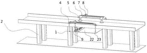
[0025] As shown in the figure, the bridge bottom surface coating device includes a slide rail groove-6 erected on the side wall of the bridge, and the two ends of the slide rail groove-6 are supported by jacks 5, and the slide rail groove-6 is equipped with The motor 7 drives the slider 8 to move back and forth on it.

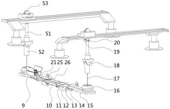
[0026] The bottom of slide block 8 is connected with upper pipe cover 51, and described upper pipe cover 51 is hingedly connected with lower pipe cover 52, and the side of institute's upper pipe cover 51 is equipped with driving lower pipe cover 52 rotating motor two 18; 8, a wire rope retractable machine 53 is installed above; the steel wire rope 17 passes through the upper pipe sleeve 51 and the lower pipe sleeve 52, and one end is connected with the wire rope retractable machine 53, and the other end is connected with a slot seat 16; There are slotted holes for the lower sleeve 52 to be inserted. The device below is that the wire rope retractor 53 controls ...

Embodiment 2

[0038] As shown in the figure, the bridge bottom surface coating device includes a slide rail groove-6 erected on the side wall of the bridge, and the two ends of the slide rail groove-6 are supported by jacks 5, and the slide rail groove-6 is equipped with The motor 7 drives the slider 8 to move back and forth on it.

[0039] The bottom of slide block 8 is connected with upper pipe cover 51, and described upper pipe cover 51 is hingedly connected with lower pipe cover 52, and the side of institute's upper pipe cover 51 is equipped with driving lower pipe cover 52 rotating motor two 18; 8, a wire rope retractable machine 53 is installed above; the steel wire rope 17 passes through the upper pipe sleeve 51 and the lower pipe sleeve 52, and one end is connected with the wire rope retractable machine 53, and the other end is connected with a slot seat 16; There are slotted holes for the lower sleeve 52 to be inserted. The device below is that the wire rope retractor 53 controls ...


PUM


Abstract

The invention discloses a bridge bottom surface coating device comprising first sliding rail groove erected in the side walls of a bridge. Jack supports are mounted at the two ends of the first sliding rail grooves; and sliding blocks driven by motors to move back and forth on the first sliding rail grooves are mounted on the first sliding rail grooves. The bridge bottom surface coating device is characterized in that upper pipe sleeves are connected to the lower portions of the sliding blocks; the upper pipe sleeves are connected with lower pipe sleeves in a hinged mode; second motors driving the lower pipe sleeves to rotate are mounted on the side edges of the upper pipe sleeves; steel wire rope folding-unfolding machines are mounted on the sliding blocks; steel wire ropes penetrate through the upper pipe sleeves and the lower pipe sleeves, one ends of the steel wire ropes are connected with the steel wire rope folding-unfolding machines, and the other ends of the steel wire ropes are connected with clamping groove seats; and groove holes allowing the lower pipe sleeves to be inserted are formed in the clamping groove seats. The bridge bottom surface coating device has the beneficial effects that painting and coating operation on the wall faces of the bottom of the elevated bridge is automatically achieved through the structure, the speed is high, the mechanization degree is high, the risk of manual operation is reduced, the economical cost is reduced, and the bridge bottom surface coating device is suitable for being used and popularized.

Description

technical field [0001] The invention relates to a bridge wall surface paint spraying device and a construction method thereof, belonging to the field of municipal engineering. Background technique [0002] Viaduct, that is, flyover bridge, a bridge. A bridge spanning valleys, rivers, roads, or other low obstacles resting on a series of narrow reinforced concrete or masonry arches with high-supported towers or pillars. After the city develops, the traffic is congested, the buildings are dense, and the streets are difficult to widen. Using this kind of bridge can evacuate the traffic density and improve the transportation efficiency. In addition, in highways or railways between cities, in order to avoid crossing with other lines, save land, and reduce subsidence of the roadbed (in some areas), this bridge can also be used without embankments. The viaduct not only refers to the physical bridge but also refers to difficulties, setbacks and so on. [0003] Disclosed as patent ...

Claims


Application Information

Patent Timeline
Patent Type & Authority Applications(China)
IPC IPC(8): B05B13/04B05B15/00B05B15/04E01D21/00
CPCB05B13/005B05B13/041B05B15/00B05B15/68B05D1/02E01D19/106E01D21/00
Inventor 成荣鹏
Owner 孙健春
Why Eureka
Try Eureka