
Path planning method and device for angular movement

A path planning and angle technology, applied in program control, instrumentation, electrical program control, etc., can solve problems such as high time consumption and low efficiency

Active Publication Date: 2019-03-12
SHANGHAI LYNAC NUMERICAL CONTROL TECH CO LTD
View PDF3 Cites 0 Cited by
  • Summary
  • Abstract
  • Description
  • Claims
  • Application Information

AI Technical Summary

Problems solved by technology

[0004] The technical problem to be solved by the present invention is to provide a path planning method and device for angular movement with less transition time and high efficiency in order to overcome the defects of more time spent and low efficiency caused by the angle transition mode in the prior art

Method used

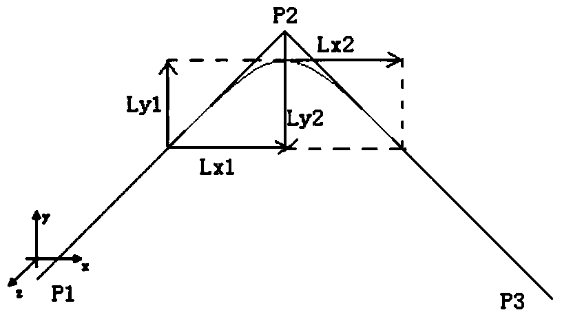
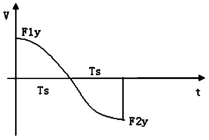

Image

  • Path planning method and device for angular movement
  • Path planning method and device for angular movement
  • Path planning method and device for angular movement

Examples


Embodiment Construction

[0056] The present invention is further illustrated below by means of examples, but the present invention is not limited to the scope of the examples.

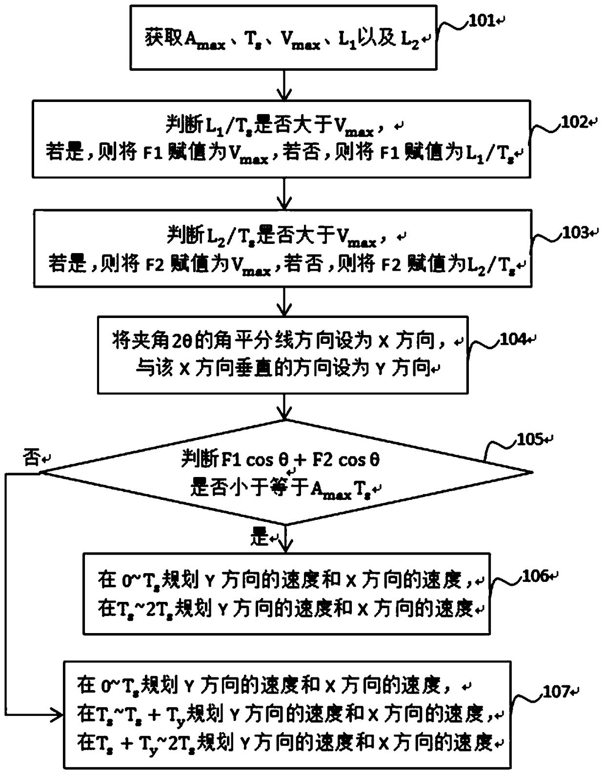
[0057] A path planning method for angular movement, the angle 2θ of the angular movement is formed by the first path and the second path, and 0°figure 1 As shown, the path planning method includes the following steps:

[0058] Step 101. Obtain the acceleration limit value A max , Acceleration change time T s , speed limit value V max , the distance L of the first path 1 and the distance L of this second path 2 ;

[0059] Step 102, judge L 1 / T s Is it greater than V max , if so, assign the speed F1 of the first midpoint as V max , if not, assign the speed F1 of the first midpoint as L 1 / T s , the first midpoint is the midpoint of the first path;

[0060] Step 103, judge L 2 / T s Is it greater than V max , if so, assign the speed F2 of the second midpoint as V max , if not, assign the speed F2 of the second midp...


PUM


Abstract

The invention discloses an included angle motion path planning method and an included angle motion path planning device. The included angle 2theta of the included angle motion is formed by a first path and a second path. The included angle motion path planning method comprises steps that acceleration limit value Amax and acceleration change time Ts are acquired; speed F1 of a first middle point and speed F2 of a second middle point are acquired, and the first middle point is the middle point of the first path, and the second middle point is the middle point of the second path; the angular bisector direction of the included angle 2theta is set to be an X direction, and a direction vertical to the X direction is set to be a Y direction; the speed of the Y direction and the speed of the X direction are planned according to a relation between F1 cos theta + F2 cos theta and Amax Ts. Compared with the prior art, the motion speed of the included angle motion between the middle point of the first path and the middle point of the second path is planned, and the acceleration is not zero during transition, and therefore the speed is changed quickly during the transition, the time of the transition is shortened, and efficiency is improved.

Description

technical field [0001] The present invention relates to the field of path planning, in particular to a path planning method and device for angular movement. Background technique [0002] With the development of the world's manufacturing industry, more and more small and medium-sized enterprises use CNC equipment for production, processing and manufacturing. The numerical control technology is to use digital information to control the mechanical movement and processing process. The early numerical control system was hardware numerical control, and now it is generally controlled by computer, that is, CNC (computer numerical control), which can control the actions of multiple numerical control equipment. [0003] The high-speed and high-precision module of the CNC system is an important part of the CNC. It is mainly aimed at the CNC commands. Through a series of forward-looking block commands, the machining trajectory in the CNC program is smoothed according to the set paramet...

Claims


Application Information

Patent Timeline
Patent Type & Authority Patents(China)
IPC IPC(8): G05B19/19
CPCG05B19/19G05B2219/37447
Inventor 方静波周明虎
Owner SHANGHAI LYNAC NUMERICAL CONTROL TECH CO LTD
Learn More