
Rotatable wheel supporting device and using method

A supporting device and wheel technology, which is applied in the field of wheel supporting devices and vehicle suspension systems, can solve problems such as large space and large turning radius, and achieve the effects of increasing utilization, meeting comfort requirements, and saving parking space

Inactive Publication Date: 2017-07-18
ZHENJIANG COLLEGE
View PDF4 Cites 4 Cited by
  • Summary
  • Abstract
  • Description
  • Claims
  • Application Information

AI Technical Summary

Problems solved by technology

[0003] The purpose of the present invention is to provide a 90-degree-rotatable vehicle suspension system and a method of use to overcome the disadvantages of large turning radius and large space required for parking in the current vehicle suspension system described in the background technology. The deficiencies in the technology make it possible for the vehicle to move directly to the parking space horizontally, and to drive out of the parking space horizontally, which greatly saves the space of the parking lot

Method used


Image

  • Rotatable wheel supporting device and using method
  • Rotatable wheel supporting device and using method
  • Rotatable wheel supporting device and using method

Examples


Embodiment Construction

[0021] In order to make the purpose and technical solution of the present invention clearer, the technical solution of the present invention will be clearly and completely described below in conjunction with the accompanying drawings of the embodiments of the present invention. Apparently, the described embodiments are some, not all, embodiments of the present invention. Based on the described embodiments of the present invention, all other embodiments obtained by persons of ordinary skill in the art without creative efforts shall fall within the protection scope of the present invention.

[0022] Those skilled in the art can understand that unless otherwise defined, all terms (including technical terms and directional terms) used herein have the same meanings as commonly understood by those of ordinary skill in the art to which the present invention belongs.

[0023] In the present invention, the normal traveling direction of the vehicle is used as a reference, the normal tra...


PUM


Abstract

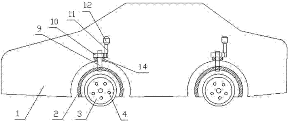
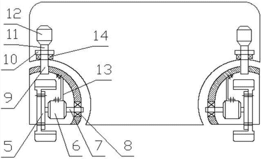
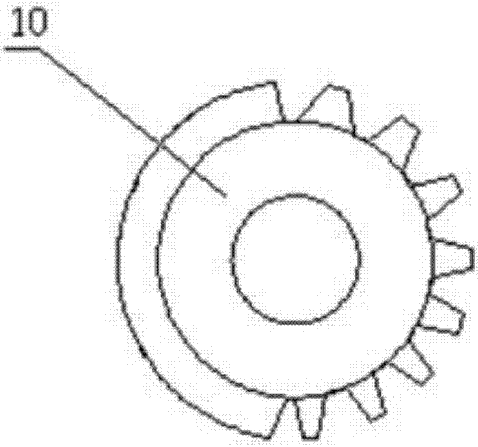
The invention provides a rotatable wheel supporting device comprising a vehicle body provided with four wheels. Ball rack shafts are installed in the positions of the four wheels of the vehicle body through ball rack shaft bearings; ball-shaped frames are fixed at the bottom ends of the ball rack shafts, and gears are connected with the top ends of the ball rack shafts in a transmission mode; the gears are connected with gear shafts in a transmission mode; the gear shafts are connected with steering motors in a transmission mode; double-shaft motors are installed on the inner sides of the ball-shaped frame through stabilizing rods; flange plates are arranged on power output shafts of the power output ends of the double-shaft motors and connected with rims of the wheels through rim bolts; speed relays and electromagnetic holding brakes are installed on brake shafts of the brake control ends of the double-shaft motors, and bearings are arranged between brake shafts of the brake control ends of the double-shaft motors and the ball-shaped frames; and the steering motors and the double-shaft motors are connected with control switches through wire harnesses. The basic problem of difficult vehicle parking is solved; at the time of parking, large turning space is not needed, and a vehicle can be parked on a parking place directly and transversely, so that a large amount of parking space is saved.

Description

technical field [0001] The invention relates to a vehicle suspension system, in particular to a rotatable wheel support device and a using method, and belongs to the technical field of automobiles. Background technique [0002] With the rapid development of my country's automobile industry, the number of automobiles in my country tends to be saturated, and subsequently, the problem of car parking is obviously prominent, and there is a problem of difficult parking. The parking space is small and the utilization rate of the parking lot is not high. Most vehicles use front-wheel steering, and the steering angle is generally only 30 degrees to 40 degrees, so the turning radius is large and the space required for parking is large. Contents of the invention [0003] The purpose of the present invention is to provide a 90-degree-rotatable vehicle suspension system and a method of use to overcome the disadvantages of large turning radius and large space required for parking in the ...

Claims


Application Information

Patent Timeline
IPC IPC(8): B60S11/00
CPCB60S11/00
Inventor 周炳强
Owner ZHENJIANG COLLEGE
Learn More