


Quick Research
Generate reliable direction feasibility study reports for your R&D in just a few steps.

Technical Q&A
Discover and master advanced knowledge NOW. Basics, ideas, possibilities, all at once.

Find Solutions
As an expert in R&D theories, this can generate solutions to your technical problems instantly.

Evaluate Feasibility
Analyze your overall solution with one click, know your potential R&D risks in advance.

Monitor Landscape
Get weekly tech updates, stay abreast of the latest tech innovations and key insights.
A laser focusing method, device and photographing equipment
A technology for laser focusing and shooting equipment, which is applied in the field of laser focusing, and can solve the problems affecting the focusing effect of shooting equipment and the constant laser beam emission power.
- Summary
- Abstract
- Description
- Claims
- Application Information
AI Technical Summary
Problems solved by technology
Method used
Image


Examples
Embodiment 1
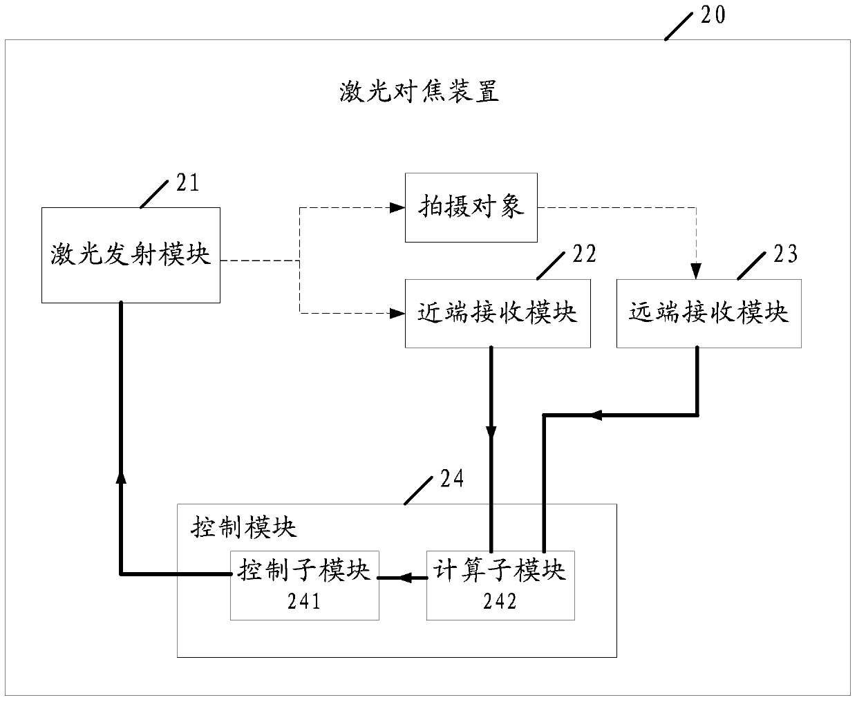
[0035] Such as figure 2 As shown, the embodiment of the present invention provides a laser focusing device 20, comprising: a laser emitting module 21, a near-end receiving module 22, a far-end receiving module 23 and a control module 24; the control module 24 includes a control sub-module 241 and a computing Submodule 242 .
[0036] Wherein, the calculation sub-module 242 is connected to the near-end receiving module 22 and the far-end receiving module 23 respectively; the control sub-module 241 is connected to the calculation sub-module 242, and the control sub-module 241 Connect the laser emitting module 21.
[0037] The laser emitting module 21 is used for emitting laser beams.
[0038] The near-end receiving module 22 is configured to receive the laser beam emitted by the laser emitting module 21 .
[0039]The remote receiving module 23 is configured to receive the far-end reflected laser light of the laser beam emitted by the laser emitting module 21 reflected by the ...
Embodiment 2
[0072] An embodiment of the present invention provides a laser focusing method, such as Figure 4 As shown, the laser focusing method includes:
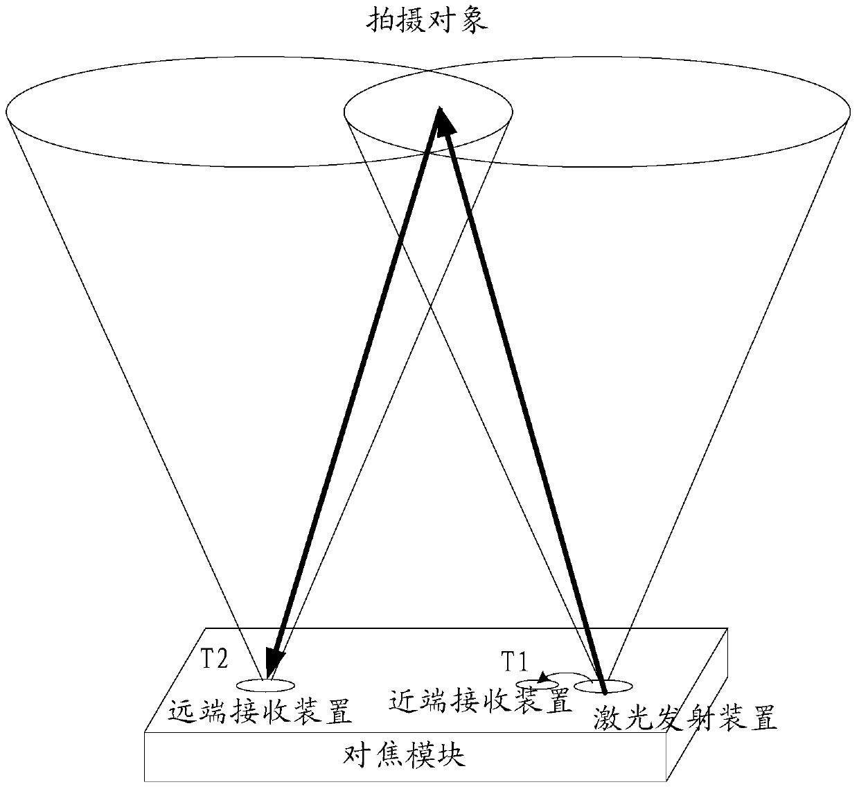
[0073] S301. The laser focusing device calculates the first transmission time. The first transmission time is the time from when the laser beam is emitted with the first transmission power to when the far-end reflected laser beam reflected by the object at the first distance is received. A distance is an effective ranging distance corresponding to the first transmit power.
[0074] The first transmission time in the embodiment of the present invention can be freely figure 2 The shown laser emitting module 21 starts to emit a laser beam with the first emission power, and then proceeds to figure 2 The shown far-end receiving module 23 receives the cut-off time of the far-end reflected laser beam reflected by the object at the first distance.
[0075] It should be noted that, since the distance between the laser emitting module 21 ...
PUM
 Abstract
Description
Claims
Application Information
 - R&D Engineer
- R&D Manager
- IP Professional
- Industry Leading Data Capabilities
- Powerful AI technology
- Patent DNA Extraction
Browse by: Latest US Patents, China's latest patents, Technical Efficacy Thesaurus, Application Domain, Technology Topic, Popular Technical Reports.
© 2024 PatSnap. All rights reserved.Legal|Privacy policy|Modern Slavery Act Transparency Statement|Sitemap|About US| Contact US: help@patsnap.com