Spark gap zero-value detector

A spark gap and detector technology, which is applied in the direction of instruments, measuring electronics, measuring devices, etc., can solve the problems of reduced judgment accuracy and increased detection time, and achieve the effect of improving detection accuracy and efficiency

Pending Publication Date: 2017-07-14
STATE GRID CORP OF CHINA +1
View PDF0 Cites 1 Cited by
  • Summary
  • Abstract
  • Description
  • Claims
  • Application Information

AI Technical Summary

Problems solved by technology

In the process of zero-value detection of porcelain insulators in transmission lines, operators generally use the spark gap test method. When the spark gap is used to detect insulators, when the carbon steel probe is close to the surface of the insulator, the electric field on the surface of the insulator will cause the surface of the probe to generate an induced charge. As a result, a local electric field is formed, and the field strength increases as the distance between the two decreases, eventually causing the insulator to discharge to the probe, accompanied by a "squeak" discharge sound, and the "squeak" discharge sound is used to judge the result. However, this sound is very similar to the discharge sound when testing a good insulator, which is likely to cause misjudgment: the corona discharge sound of the wire is very similar to the discharge sound when testing a good insulator, and it is also easy to cause misjudgment; There will be environmental noise interference such as strong winds and moving vehicles, so repeated listening is required during detection, which not only increases the detection time, but also greatly reduces the accuracy of judgment

Method used


Image

  • Spark gap zero-value detector
  • Spark gap zero-value detector

Examples


Embodiment Construction

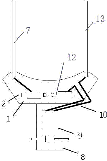
[0011] Such as figure 1 and 2 As shown, the present invention includes a spark gap zero value detector, including a handle, a support plate 1 arranged at the end of the handle, an AC motor 9 and a rotor arranged at the end of the output shaft of the AC electrode, and the support plate 1 is a half arc, the first discharge electrode 2 and the second discharge electrode 12 are fixedly arranged on the support plate 1, the first discharge electrode 2 and the second discharge electrode 12 are symmetrical along the central axis of the semi-arc, and the semi-arc support plate 1 The first probes 7 and the second probes 13 are respectively fixedly arranged at both ends, the first probes 7 are electrically connected with the first discharge electrode 2, the second probes 13 and the second electrodes 12 are respectively connected with the AC The power inlet terminals of the motor 9 are connected in series.

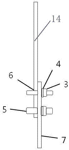
[0012] The support plate 1 is hinged with the handle bar 14, and the first and ...


PUM


Abstract

The invention discloses a spark gap zero-value detector which comprises a holding rod, a support plate, an AC motor and a rotor wing. The support plate is in a half arc shape. A first discharge electrode and a second discharge electrode are fixedly disposed on the support plate at intervals, and are symmetrical with respect to the central axis of the half arc shape. A first probe and a second probe are fixedly disposed on both end portions of the half-arc support plate respectively. An insulator is shorted by the first probe and the second probe (spark gap probe), and a gap between the first probe and the second probe is subjected to breakdown by air under the effect of the distributed voltage of the insulator. When the leakage current of the insulator flows through a detection circuit and discharges electricity at the gap, the AC motor connected in series with the detection circuit is switched on to drive the rotor wing to rotate. Thus, a discriminate signal of a test result can be represented intuitively and discharge sound is given so as to avoid an influence of noisy environment on detection result determination and greatly improve detection accuracy and efficiency.

Description

technical field [0001] The invention relates to the technical field of zero-value and low-value charged detection of ceramic insulators of power transmission lines, in particular to a spark gap zero-value detector. Background technique [0002] At present, the zero value detection of porcelain insulators in transmission lines is an important measure to measure the operating conditions of porcelain insulators. In the process of zero-value detection of porcelain insulators in transmission lines, operators generally use the spark gap test method. When the spark gap is used to detect insulators, when the carbon steel probe is close to the surface of the insulator, the electric field on the surface of the insulator will cause the surface of the probe to generate an induced charge. As a result, a local electric field is formed, and the field strength increases as the distance between the two decreases, eventually causing the insulator to discharge to the probe, accompanied by a "s...

Claims


Application Information

Patent Timeline
IPC IPC(8): G01R31/12
CPCG01R31/1245
Inventor 王维李占军田晓鹏石朋飞王红旗
Owner STATE GRID CORP OF CHINA
Why Eureka
Try Eureka