
Movable-ceiling solar bus stop shelter

A technology of solar energy and bus shelters, applied in the integration of renewable energy, roofs, sustainable buildings, etc., can solve the problems of short service life, frequent cleaning, and small area of ​​solar shelters for rain protection, so as to prolong life and reduce labor The effect of increasing the effective rain-shading area

Inactive Publication Date: 2017-07-14
CHENGDU ZHENZHONG ELECTRIC
View PDF0 Cites 7 Cited by
  • Summary
  • Abstract
  • Description
  • Claims
  • Application Information

AI Technical Summary

Problems solved by technology

[0003] The purpose of the present invention is to provide a solar bus shelter with a movable roof, which solves the problem of short service life and frequent cleaning of the solar panel of the traditional solar bus shelter with a movable roof because it has been left outside for a long time , At the same time, it also solves the problem of the small use area of ​​the solar car shelter with a movable roof

Method used


Image

  • Movable-ceiling solar bus stop shelter
  • Movable-ceiling solar bus stop shelter
  • Movable-ceiling solar bus stop shelter

Examples


Embodiment 1

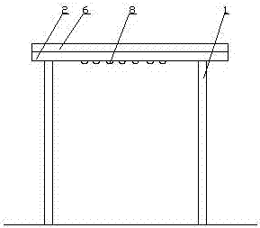
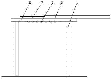
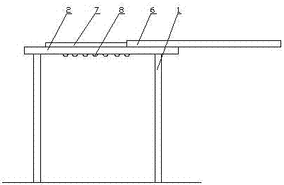
[0035] Such as figure 1 , 2 As shown in , 3 and 4, the solar bus shelter with a movable roof includes a column 1 and a roof 2. There are four columns 1 and they are installed on the ground. The roof 2 is fixedly installed on the top of the column 1. The left and right sides of the surface are provided with linear motors, and the linear motor includes a mover seat 4 and a slide rail 5, wherein the slide rail 5 is fixedly connected to the top plate 2, and the mover seat 4 is slidably connected to the slide rail 5; there is a moving cover plate 6 Set on the top plate 2, the moving cover plate 6 is fixedly connected to the mover seat 4 on the linear motor at the left and right edges of the top plate 2, and the moving cover plate 6 is moved out of the top plate 2 through the sliding connection between the mover seat 4 and the slide rail 5, And constitute a rain shield, a solar cell panel placement cavity is left between the mobile cover plate 6 and the top plate 2; An electric la...

Embodiment 2

[0037] Compared with embodiment 1, this embodiment optimizes the column 1, wherein a switch of the linear motor is also installed on one of the column 1, and the switch is electrically connected with the linear motor and the battery respectively. In this embodiment, the switch is convenient for the waiting staff to control the linear motor. Motor use.

Embodiment 3

[0039] Such as Figure 4 As shown, compared with Example 1, the present embodiment optimizes the top plate 2, the top plate 2 is equipped with a stable support 10, and the solar cell panel 7 is installed on the top plate 2 through the stable support 10. In this embodiment, the stable support 10 can The solar cell panel 7 is installed on the roof 2 more stably, and the stable support 10 can improve the position of the solar cell panel 7, so that the solar cell panel 7 is not disturbed by accumulated water on the roof 2 .


PUM


Abstract

The invention discloses a movable-ceiling solar bus stop shelter which comprises stand columns and a top plate. The top plate is fixedly mounted at the tops of the stand columns. Linear motors are arranged at the edges of the left side and the right side of the top face of the top plate correspondingly. A movable cover plate is arranged on the top plate. A solar cell panel is arranged in a solar cell panel storage cavity and mounted on the top plate. Electric lamps are mounted on the lower portion of the top plate. Storage batteries are mounted in the stand columns. The movable-ceiling solar bus stop shelter has the beneficial effects that the movable cover plate can be used for enlarging the effective rain-sheltering use area of the bus stop shelter and can also resist foreign bodies such as sand blown by the wind which can damage the solar cell panel, and the service life of the shelter is accordingly prolonged; and when the solar cell panel is not used, the movable cover plate can be used for preventing dust from falling onto the solar cell panel, accordingly frequent cleaning by working staff is avoided, and the labor capacity is reduced.

Description

technical field [0001] The invention relates to a solar bus shelter with a movable ceiling, in particular to a solar bus shelter with a movable ceiling. Background technique [0002] The traditional solar bus shelter with a movable roof is exposed to the wind and sun for a long time because the solar panels are exposed for a long time, so the service life is short, and it needs to be scrubbed frequently during use, which is very troublesome. Contents of the invention [0003] The purpose of the present invention is to provide a solar bus shelter with a movable roof, which solves the problem of short service life and frequent cleaning of the solar panel of the traditional solar bus shelter with a movable roof because it has been left outside for a long time , It also solves the problem of the small area of ​​the solar car shelter with a movable roof for sheltering from rain. [0004] In order to solve the above-mentioned technical problems, the present invention adopts...

Claims


Application Information

Patent Timeline
Patent Type & Authority Applications(China)
IPC IPC(8): E04H1/12E04B7/16H02S20/24H02S40/10
CPCE04B7/166E04H1/1211H02S20/24H02S40/10Y02B10/10Y02E10/50
Inventor 王刚胡国波聂海涛
Owner CHENGDU ZHENZHONG ELECTRIC
Learn More