New energy vehicle charging device capable of being automatically controlled

A new energy vehicle and charging device technology, applied in electric vehicle charging technology, electric vehicles, charging stations, etc., can solve the problems of easy arcing, user safety accidents, casualties, etc. Effectiveness of work efficiency and improved safety

Active Publication Date: 2017-07-14
JIANGSU XIYI HIGH NEW DISTRICT TECH DEV CO LTD
View PDF5 Cites 12 Cited by
  • Summary
  • Abstract
  • Description
  • Claims
  • Application Information

AI Technical Summary

Problems solved by technology

Electric vehicles are inseparable from charging piles, but in the process of charging electric vehicles with existing charging piles, they are all manually plugged and unplugged by personnel. During the plugging and unplugging process, the charging gun head is prone to arc due to the influence of voltage, and the generation of arc is easy to cause The electric shock of the user has a certain potential danger to the user, which will cause safety accidents and cause casualties, and the force of the personnel is unstable when plugging in, which may easily lead to equipment damage. In addition, the protective cover outside the charging power supply part of the traditional charging pile needs Manual opening and closing has a great potential safety hazard. If the protective cover is lost or damaged, the charging and power supply part is exposed, which may easily cause electric shock accidents.

Method used


Image

  • New energy vehicle charging device capable of being automatically controlled
  • New energy vehicle charging device capable of being automatically controlled
  • New energy vehicle charging device capable of being automatically controlled

Examples


Embodiment Construction

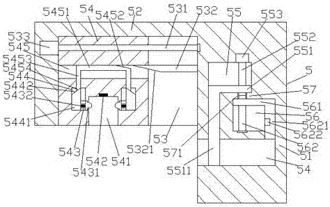
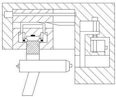
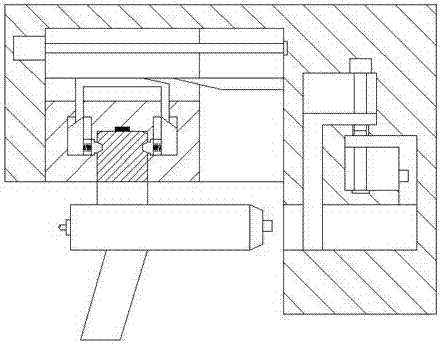
[0025] Such as Figure 1-Figure 8 As shown, an automatically controlled new energy vehicle charging device of the present invention includes a charging pile body 5 and a charging gun 6. The charging pile body 5 includes a power supply part 51 and is fixedly arranged on the upper left side of the power supply part 51. The execution part 52 of the power supply part 51 is provided with an insertion groove 54 in the end surface on the lower left side of the power supply part 51, and a first sliding cavity 56 is arranged in the power supply part 51 above the right side of the insertion groove 54. A second sliding chamber 55 is provided in the power supply part 51 on the upper left side of the first sliding chamber 56, and a second sliding chamber 55 is provided between the inner top wall on the left side of the first sliding chamber 56 and the inner bottom wall on the right side of the second sliding chamber 55. There is a partition 57, the first sliding chamber 56 is provided with...


PUM


Abstract

The invention discloses a new energy vehicle charging device capable of being automatically controlled. The new energy vehicle charging device capable of being automatically controlled comprises a charging pile body and a charging gun; the charging pile body comprises a power supply part and an executing part which is fixedly arranged above the left side of the power supply part; an inserting groove is formed in the end surface of downside of the left side of the power supply part; a first slide chamber is formed in a position, above the right side of the inserting groove, in the power supply part; a second slide chamber is formed in a position, above the left side of the first slide chamber, in the power supply part; a partition plate is arranged between the inner top wall of the left side of the first slide chamber and the inner bottom wall of the right side of the second slide chamber; a first screw rod which is arranged to extend upward is arranged in the first slide chamber; a second screw rod which is arranged to extend downward is arranged in the second slide chamber; a first slide block is connected to the first screw rod in a matched manner; a second slide block is connected to the second screw rod in a matched manner; an executing slide groove is formed in the executing part; and a transmission screw rod which is arranged to extend from left to right is arranged in the executing slide groove. The new energy vehicle charging device capable of being automatically controlled has the advantages that the structure is simple; the operation is convenient; the inserting work can be automatically finished so that the efficiency is enhanced; and due to the opening of a protective plate and extending-out of a power supply jack, the safety is enhanced.

Description

technical field [0001] The invention relates to the technical field of new energy vehicle charging, in particular to a new energy vehicle charging device capable of automatic control. Background technique [0002] With the gradual depletion of oil resources, electric vehicles have been well developed in recent years. Compared with gasoline vehicles, electric vehicles are more energy-saving and environmentally friendly, so they are being promoted by countries all over the world. Electric vehicles are inseparable from charging piles, but in the process of charging electric vehicles with existing charging piles, they are all manually plugged and unplugged by personnel. During the plugging and unplugging process, the charging gun head is prone to arc due to the influence of voltage, and the generation of arc is easy to cause The electric shock of the user has a certain potential danger to the user, which will cause safety accidents and cause casualties, and the force of the per...

Claims


Application Information

Patent Timeline
IPC IPC(8): B60L11/18
CPCB60L53/30B60L53/31Y02T10/70Y02T10/7072Y02T90/12
Inventor 陈柏海
Owner JIANGSU XIYI HIGH NEW DISTRICT TECH DEV CO LTD
Why Eureka
Try Eureka