
Practical welding device

A welding device and practical technology, applied in auxiliary devices, welding equipment, auxiliary welding equipment and other directions, can solve the problems of hidden safety hazards, simple fixing methods, low stability, etc., and achieve improved insertion stability, convenient operation, and structure. simple effect

Inactive Publication Date: 2018-06-29
CIXI ZHIJIANG MECHANICAL TECH CO LTD
View PDF0 Cites 0 Cited by
  • Summary
  • Abstract
  • Description
  • Claims
  • Application Information

AI Technical Summary

Problems solved by technology

[0002] When welding large workpieces, the welding equipment is generally fixed, and the pipe fittings are fixed on the frame and the frame moves randomly. The existing fixed welding equipment has a simple fixing method and low stability. Hidden danger

Method used


Image

  • Practical welding device
  • Practical welding device
  • Practical welding device

Examples


Embodiment Construction

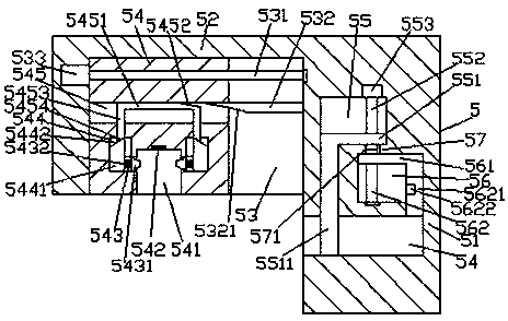
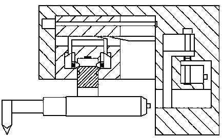
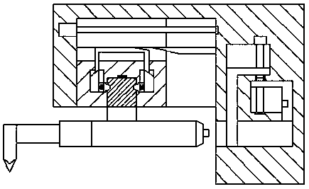
[0026] Such as Figure 1-Figure 8 As shown, a practical welding device of the present invention includes a fixed base 5 and an electric welding torch 6. The fixed base 5 includes a power feeding base 51 and an operation part 52 fixedly arranged on the upper left side of the power feeding base 51. An insertion slot 54 is provided in the end face of the lower left side of the power supply seat 51, and a first sliding cavity 56 is provided in the power supply seat 51 above the right side of the insertion slot 54. The first sliding cavity 56, a second sliding chamber 55 is provided in the power feeding seat 51 on the upper left side, and a baffle plate is provided between the inner top surface on the left side of the first sliding chamber 56 and the inner bottom surface on the right side of the second sliding chamber 55. 57, the first sliding cavity 56 is provided with a first screw rod 562 extending upward, and the second sliding cavity 55 is provided with a second screw rod 552 ...


PUM


Abstract

The invention discloses a practical welding device. The practical welding device comprises a fixing base and an electric welding gun. The fixing base comprises a power supply base and an operation part fixedly arranged at the upper portion of the left side of the power supply base. An inserting groove is formed in the end face of the lower portion of the left side of the power supply base. A firstsliding cavity is formed in the part, above the right side of the inserting groove, of the power supply base. The part, above the left side of the first sliding groove, of the power supply base is internally provided with a second sliding cavity. A baffle is arranged between the inner top face of the left side of the first sliding cavity and the inner bottom face of the right side of the second sliding cavity. The first sliding cavity is internally provided with a first spiral rod extending upwards. The second sliding cavity is internally provided with a second spiral rod extending downwards.The first spiral rod is connected with a first sliding block in a spiral pattern fit manner. The second spiral rod is connected with a second sliding block in a spiral pattern fit manner. A first sliding groove is formed in the operation part and internally provided with a conduction spiral rod extending left and right. The practical welding device is simple in structure, convenient to operate and capable of achieving automatic inserting work completion, efficiency improving, first baffle opening and power supply circular hole stretching out, and safety is improved.

Description

technical field [0001] The invention relates to the field of welding technology, in particular to a practical welding device. Background technique [0002] When welding large workpieces, the welding equipment is generally fixed, and the pipe fittings are fixed on the frame for welding. Hidden danger. Contents of the invention [0003] The technical problem to be solved by the present invention is to provide a practical welding device, which can solve the above-mentioned problems in the prior art. [0004] The present invention is achieved through the following technical solutions: A practical welding device of the present invention includes a fixed base and an electric welding torch, the fixed base includes a power supply base and an operation fixedly arranged above the left side of the power supply base part, the end face of the lower left side of the power feeding seat is provided with an insertion groove, and the power feeding seat above the right side of the insertio...

Claims


Application Information

Patent Timeline
IPC IPC(8): B23K37/02
CPCB23K37/02
Inventor 刘建华
Owner CIXI ZHIJIANG MECHANICAL TECH CO LTD
Learn More