
Agricultural fertilizing device

A fertilization device and agricultural technology, applied in fertilization devices, agriculture, fertilizer distributors, etc., can solve problems such as difficulty in automation equipment, production and economic decline, and impact on fertilization progress, so as to reduce labor load and reduce manufacturing and maintenance costs , Increase the effect of practicality

Inactive Publication Date: 2017-07-14
王裕迪
View PDF4 Cites 42 Cited by
  • Summary
  • Abstract
  • Description
  • Claims
  • Application Information

AI Technical Summary

Problems solved by technology

However, before fertilizing crops, it is necessary to mix ingredients and fertilizers with different nutrients together and use them after stirring evenly. In some large planting bases, due to the wide planting area, automatic stirring devices are used to improve mixing efficiency and speed up fertilization progress. Self-employed planting in my country occupies a considerable proportion in agricultural planting. For these self-employed individuals, due to the relatively insufficient economy, it is difficult to invest in automation equipment. Traditional manual mixing has many defects such as low efficiency, strong odor, and uneven mixing. It is difficult to meet the needs of fertilization, which seriously affects the progress of fertilization, resulting in a decline in production and economy. There are major disadvantages and cannot meet the existing needs

Method used


Image

  • Agricultural fertilizing device
  • Agricultural fertilizing device
  • Agricultural fertilizing device

Examples


Embodiment Construction

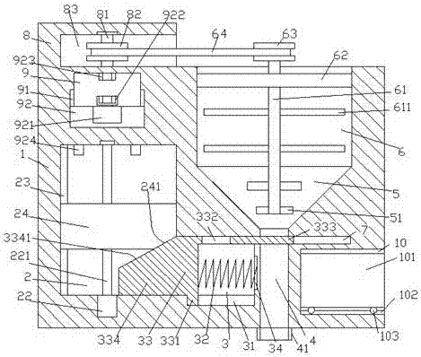
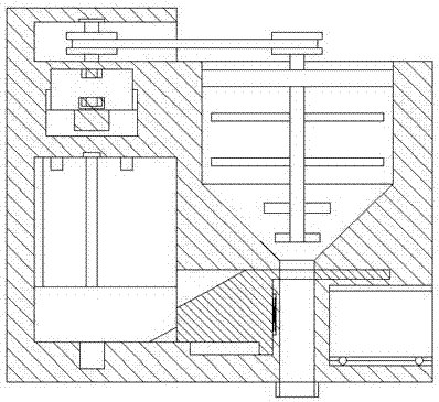
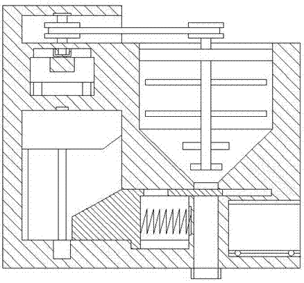
[0023] Such as Figure 1-Figure 5 As shown, an agricultural fertilization device of the present invention includes a box body 1, a first sliding chamber 2 is provided inside the left side of the box body 1, and a first guide guide is provided on the left side inner wall of the first sliding chamber 2. Sliding groove 23, the box body 1 on the right side of the first sliding chamber 2 is provided with a second sliding chamber 3 communicating with the first sliding chamber 2, and the second sliding chamber 3 The box body 1 on the right side is provided with a discharge groove 4 extending up and down, and the top of the second sliding chamber 3 is provided with a switch groove 7 that penetrates the discharge groove 4 and extends to the right. The top of the discharge groove 4 is provided with a bucket-shaped part 5, the top of the bucket-shaped part 5 is provided with a feeding part 6, and the box body 1 above the first slide chamber 2 is provided with a third slide chamber 9. Th...


PUM


Abstract

The invention discloses an agricultural fertilizing device. The a agricultural fertilizing device comprises a box body; a first sliding chamber is arranged in the left side of the box body; a first guide moving groove is arranged on the inner wall of the left side of the first sliding chamber; a second sliding chamber communicated with the first sliding chamber is arranged in the box body on the right side of the first sliding chamber; an arranging delivering groove is arranged in the box body on the right side of the second sliding chamber, wherein the arranging delivering groove is extended upward and downward; the top of the second sliding chamber is provided with a switch groove, wherein the arranging delivering groove is penetrated by the switch groove, and the switch groove is extended rightward; the top of the arranging delivering groove is provided with a bucket-shaped part; the top of the bucket-shaped part is provided with a material supplying part; a third sliding chamber is arranged in the box body above the first sliding chamber; third guide moving grooves are arranged on the left side inner wall and the right side inner wall of the third sliding chamber in a corresponding manner; a spiral rod is arranged in the first sliding chamber; the bottom of the spiral rod is connected with a first electromotor; and the spiral rod is connected with a top block via screw threads. The structure of the agricultural fertilizing device is simple; design is reasonable; operation is simple; manufacturing and maintenance cost is low; the agricultural fertilizing device is suitable for individual farmers to use; stirring and discharging can be controlled automatically; stirring is more uniform; labor intensity is reduced; and fertilizing efficiency is increased.

Description

technical field [0001] The invention relates to the technical field of agricultural equipment, in particular to an agricultural fertilization device. Background technique [0002] Agricultural fertilization is an indispensable and important measure in agricultural planting, and it is an important guarantee related to output and economic benefits. However, before fertilizing crops, it is necessary to mix ingredients and fertilizers with different nutrients together and use them after stirring evenly. In some large planting bases, due to the wide planting area, automatic stirring devices are used to improve mixing efficiency and speed up fertilization progress. Self-employed planting in my country occupies a considerable proportion in agricultural planting. For these self-employed individuals, due to the relatively insufficient economy, it is difficult to invest in automation equipment. Traditional manual mixing has many defects such as low efficiency, strong odor, and uneven m...

Claims


Application Information

Patent Timeline
IPC IPC(8): A01C15/00A01C15/12
CPCA01C15/005A01C15/12
Inventor 王裕迪
Owner 王裕迪
Learn More