A multifunctional sowing and fertilizing machine

A fertilizer applicator and multi-functional technology, which is applied to fertilizers and planting equipment, etc., can solve the problems of synchronous interplanting that are prone to blockage and poor working stability, and achieve the effect of ensuring stability and improving efficiency.

Inactive Publication Date: 2017-07-14
奥林精密机械科技(长兴)有限公司
View PDF1 Cites 1 Cited by
  • Summary
  • Abstract
  • Description
  • Claims
  • Application Information

AI Technical Summary

Problems solved by technology

[0006] The purpose of the present invention is to address the deficiencies of the prior art, to overcome the existing equipment that does not meet the requirements of synchronous interleaved interplanting of two plants and to ensure equal spacing during the process of interplanting and easy occurrence of material blockage during sowing and fertilization. The problem of poor stability

Method used


Image

  • A multifunctional sowing and fertilizing machine
  • A multifunctional sowing and fertilizing machine
  • A multifunctional sowing and fertilizing machine

Examples


Embodiment 1

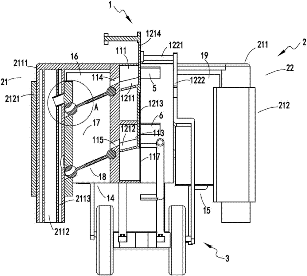
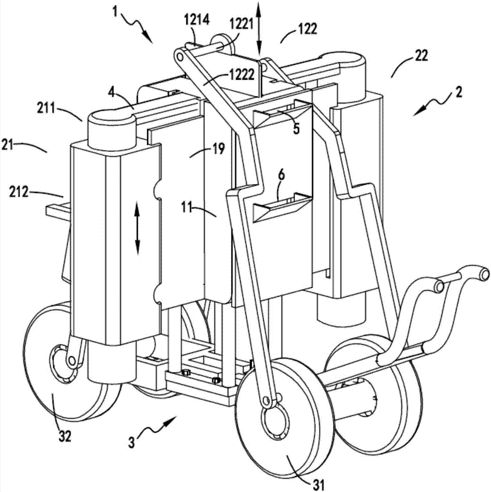
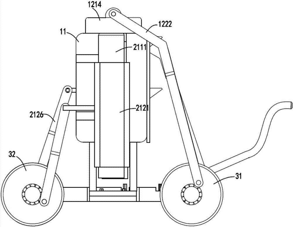
[0041] figure 1 It is a partial cut-away schematic diagram of a multifunctional seeding and fertilizing machine, figure 2 It is a schematic diagram of the structure of the multifunctional seeding and fertilizing machine, image 3 It is a schematic diagram of the side view of the multifunctional seeding and fertilizing machine, Figure 4 It is a cut-away schematic diagram of a multifunctional seeding and fertilizing machine, Figure 5 It is an enlarged schematic diagram of part of the structure of the multifunctional seeding and fertilizing machine, Image 6 It is a partial structural diagram of the multifunctional seeding and fertilizing machine, Figure 7 It is a schematic diagram of the enlarged structure of the rotating discharge device, Figure 8is a structural schematic diagram of output mechanism a or output mechanism b, Figure 9 It is a structural schematic diagram of the feeding mechanism a and the feeding mechanism b, Figure 10 is the schematic diagram of the...

Embodiment 2

[0055] Such as figure 1 , figure 2 , image 3 , Figure 4 , Figure 5 , Image 6 , Figure 7 , Figure 8 , Figure 9 , Figure 10 with Figure 11 As shown, the components that are the same as or corresponding to those in the first embodiment are marked with the corresponding reference numerals in the first embodiment. For the sake of simplicity, only the differences from the first embodiment will be described below. The difference between the second embodiment and the first embodiment is that the power device 122 includes a fixed shaft 1221 arranged on the upper end of the lifting plate 1214, one end is rotatably arranged on the end of the fixed shaft 1221 and the other end is eccentrically and rotatably arranged The transmission rod a1222 on the front wheel 31 of the cart 3; the transmission unit 2122 includes a support shaft 2125 fixed on the side of the sliding sleeve 2121 and one end is rotatably arranged on the end of the support shaft 2125 and the other end is ...


PUM


Abstract

The invention relates to a multifunctional seeding and fertilizing machine, comprising a supply part, the supply part includes a material box, a feeding mechanism a, a material feeding mechanism b, a buffer mechanism a and a buffer mechanism b, and the material box is fixedly arranged on a trolley. A seed bin a, a seed bin b and a fertilizer bin are provided, and the feeding mechanism a sends the seed a and fertilizer in the seed bin a and the fertilizer bin to the buffer mechanism a, and the feeding mechanism b sends the seed b and the seed b in the seed bin a and the fertilizer bin and The fertilizer is sent into the buffer mechanism b; the output part, the output part includes the output mechanism a and the output mechanism b, the output mechanism a and the output mechanism b both include a lead-out device and a control device, and the control device controls the buffer mechanism a and the fertilizer in the buffer mechanism b and The seed b enters the export device; it overcomes the problems that the existing equipment does not satisfy the synchronous staggered interplanting of two plants and can ensure equal spacing during the interplanting process, and the problems of material blockage and poor working stability are easy to occur in the process of sowing and fertilizing.

Description

technical field [0001] The invention relates to the technical field of agricultural equipment, in particular to a multifunctional seeding and fertilizing machine. Background technique [0002] Many crops need to be fertilized when they are sown. Most of the existing equipment work separately for sowing and fertilization. There are also some integrated equipment that perform sowing and fertilization together, but these equipments have unstable supply and output of seeds and fertilizers. In some cases, it is prone to blockage, resulting in some areas not being sown and fertilized, and it is also difficult to control the spacing of sowing and fertilizing, which will affect the growth of later crops. In addition, in the case of some interplanting of two plants, it is more difficult for existing equipment to achieve Require. [0003] A Chinese utility model patent with the authorized announcement number CN205093137U discloses a planting and fertilizing integrated machine. The de...

Claims


Application Information

Patent Timeline
Patent Type & Authority Applications(China)
IPC IPC(8): A01C7/06
CPCA01C7/06
Inventor 干贤忠
Owner 奥林精密机械科技(长兴)有限公司
Why Eureka
Try Eureka