
A driving method of a liquid crystal display panel and a liquid crystal display panel

A technology for a liquid crystal display panel and a driving method, which is applied to static indicators, nonlinear optics, instruments, etc., can solve problems such as affecting the display quality of the liquid crystal display panel and lowering the voltage, so as to improve the display quality and reduce the frequency of charging and discharging. Effect

Active Publication Date: 2019-02-12
TCL CHINA STAR OPTOELECTRONICS TECH CO LTD
View PDF6 Cites 0 Cited by
  • Summary
  • Abstract
  • Description
  • Claims
  • Application Information

AI Technical Summary

Problems solved by technology

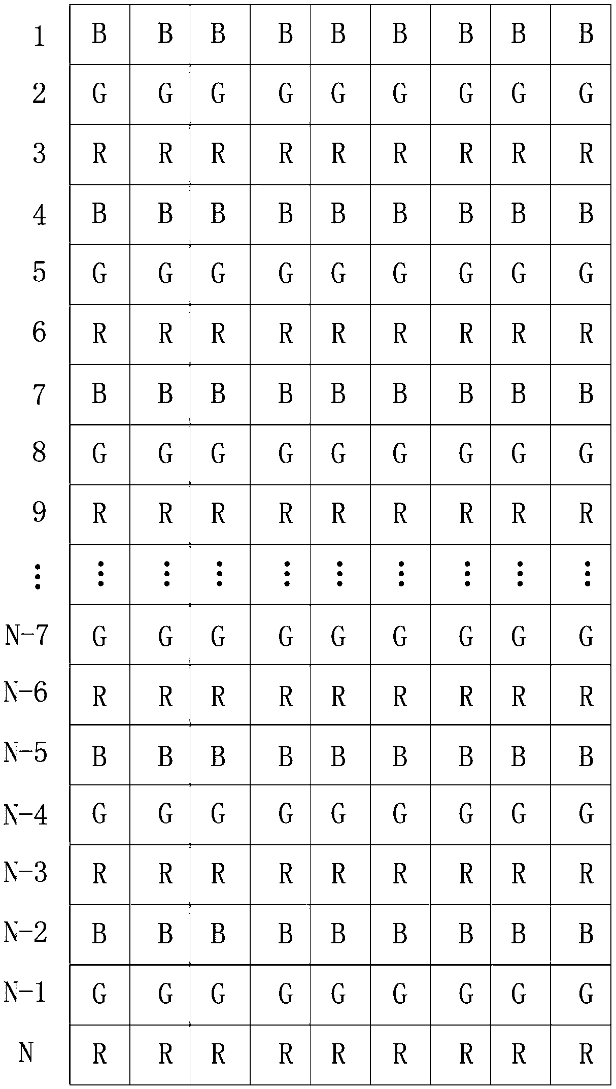
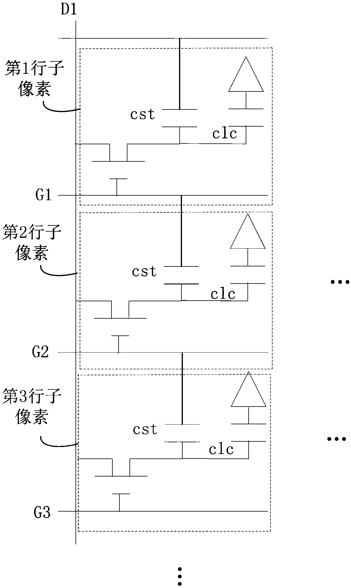
like figure 2 As shown, when driving, the sub-pixels in the second row are first driven. At this time, the scanning line G1 corresponding to the sub-pixels in the first row connected to the other end of the liquid crystal capacitor cst of the sub-pixels in the second row is turned off. The charge conservation in the sub-pixels of the second row, and then when the sub-pixels of the first row are driven, the scanning line G1 corresponding to the sub-pixels of the first row is opened, and due to the coupling effect of the storage capacitor cst of the sub-pixels of the second row, the second row The voltage of the sub-pixels is pulled down, and this phenomenon is repeated in the sub-pixels of the second row, the sub-pixels of the fifth row, the sub-pixels of the eighth row, ..., the sub-pixels of the N-5th row and the N-2th row on the sub-pixels, thereby affecting the display quality of the LCD panel

Method used


Image

  • A driving method of a liquid crystal display panel and a liquid crystal display panel
  • A driving method of a liquid crystal display panel and a liquid crystal display panel
  • A driving method of a liquid crystal display panel and a liquid crystal display panel

Examples


Embodiment Construction

[0030] In order to further illustrate the technical means adopted by the present invention and its effects, the following describes in detail in conjunction with preferred embodiments of the present invention and accompanying drawings. Apparently, the described embodiments are only some of the embodiments of the present invention, but not all of them. Based on the embodiments of the present invention, all other embodiments obtained by persons of ordinary skill in the art without creative efforts fall within the protection scope of the present invention.

[0031] The present invention provides a method for driving a liquid crystal display panel. The liquid crystal display panel used for driving by the method adopts a three-gate structure, that is, each sub-pixel in each pixel is arranged along the column direction, and the sub-pixels of the same color in each sub-pixel are Arranged in the same row, one scanning line is set corresponding to each row of sub-pixels, and one data l...


PUM


Abstract

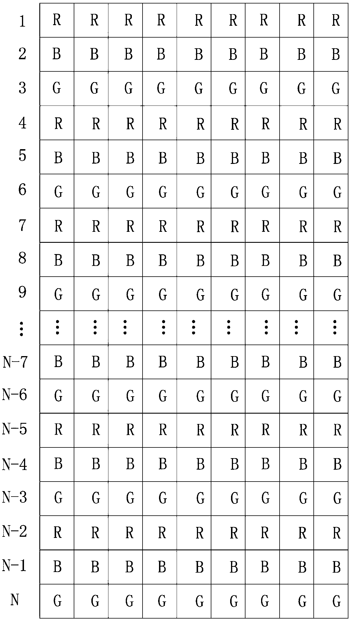
Disclosed are a driving method for a liquid crystal display panel, and a liquid crystal display panel. The liquid crystal display panel comprises a plurality of pixels arranged in an array, wherein each pixel comprises a red sub-pixel, a green sub-pixel and a blue sub-pixel, which are arranged in a column; and in each pixel, the blue sub-pixel is located between the red sub-pixel and the green sub-pixel, and is matched with a specific scanning sequence , so as to set a corresponding sub-pixel with capacitance coupling to be a blue sub-pixel, to which a human eye is less sensitive.

Description

technical field [0001] The invention relates to the field of display technology, in particular to a driving method of a liquid crystal display panel and the liquid crystal display panel. Background technique [0002] The liquid crystal display panel has many advantages such as thin body, power saving, and no radiation, and has been widely used. Such as: LCD TV, mobile phone, personal digital assistant (PDA), digital camera, computer screen or notebook computer screen, etc., occupy a dominant position in the field of flat panel display. [0003] Existing liquid crystal display panels often adopt a tri-gate (Tri-gate) structure in order to reduce costs, refer to figure 1 , figure 1 It is a schematic diagram of an existing liquid crystal display panel. Such as figure 1 As shown, the liquid crystal display panel adopting this structure includes a plurality of sub-pixels arranged in an array, and the sub-pixels include red sub-pixels R, green sub-pixels G and blue sub-pixels ...

Claims


Application Information

Patent Timeline
Patent Type & Authority Patents(China)
IPC IPC(8): G09G3/36G02F1/1343
CPCG02F1/134309G02F2201/52G09G3/3607
Inventor 陈宥烨何振伟吴宇何涛
Owner TCL CHINA STAR OPTOELECTRONICS TECH CO LTD
Learn More