A rotary liquid supply device

A technology of liquid supply and rotating shaft, applied in the field of rotating liquid supply, can solve the problems of the overall structure of the centrifuge is not compact, the axial dimension is long, etc., and achieve the effects of low pressure, small length, and easy processing accuracy.

Active Publication Date: 2018-09-11
张嗣远
View PDF5 Cites 0 Cited by
  • Summary
  • Abstract
  • Description
  • Claims
  • Application Information

AI Technical Summary

Problems solved by technology

However, the moving shaft of this mechanism is docked with the screw rod and a rotating nut is set on the frame to drive the screw rod to move. The axial dimension of the turning bag mechanism is relatively long, resulting in an uncompact overall structure of the centrifuge.

Method used


Image

  • A rotary liquid supply device
  • A rotary liquid supply device
  • A rotary liquid supply device

Examples


Embodiment Construction

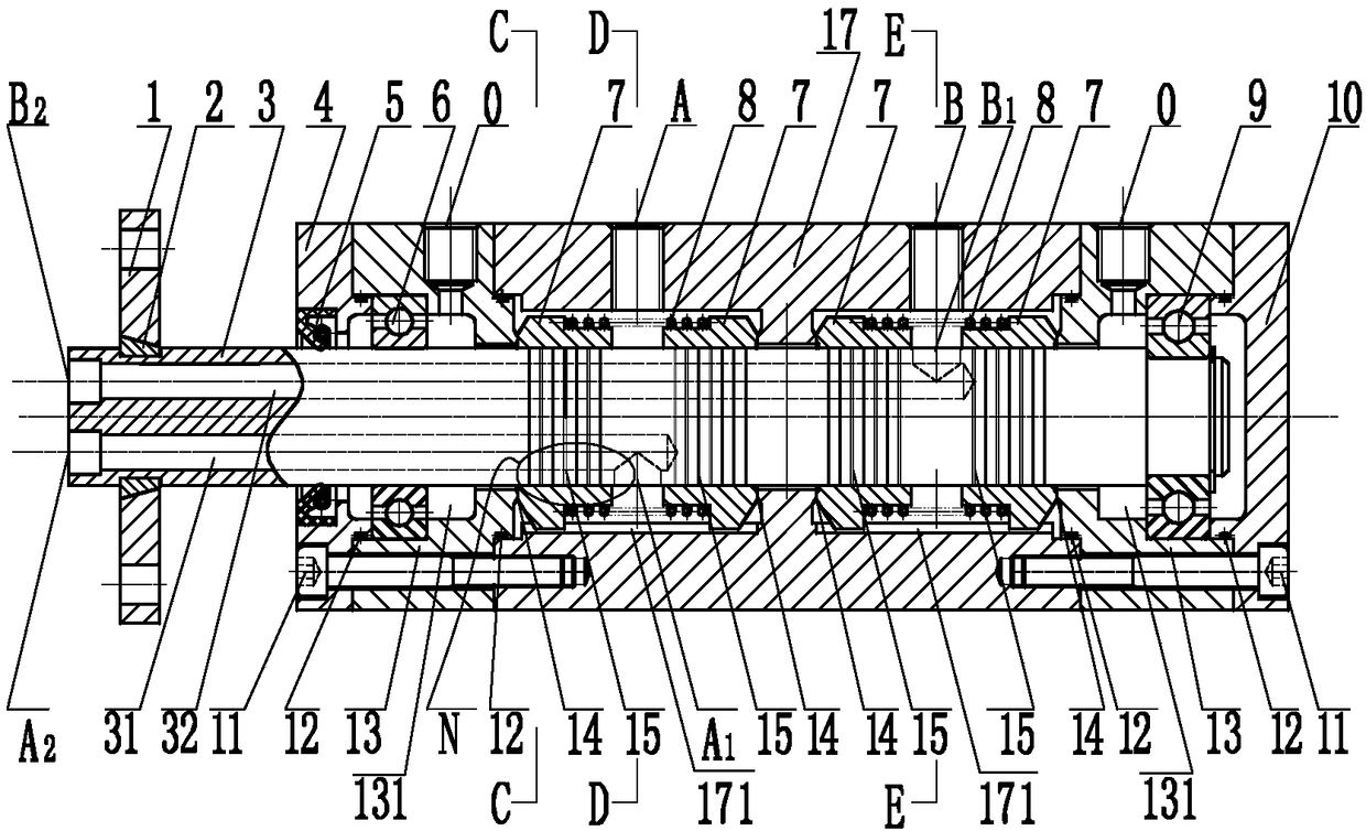
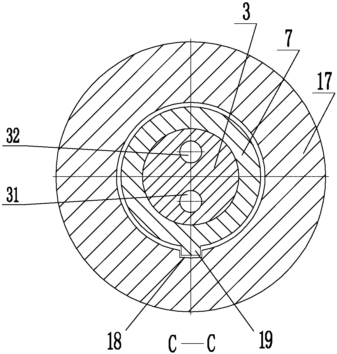
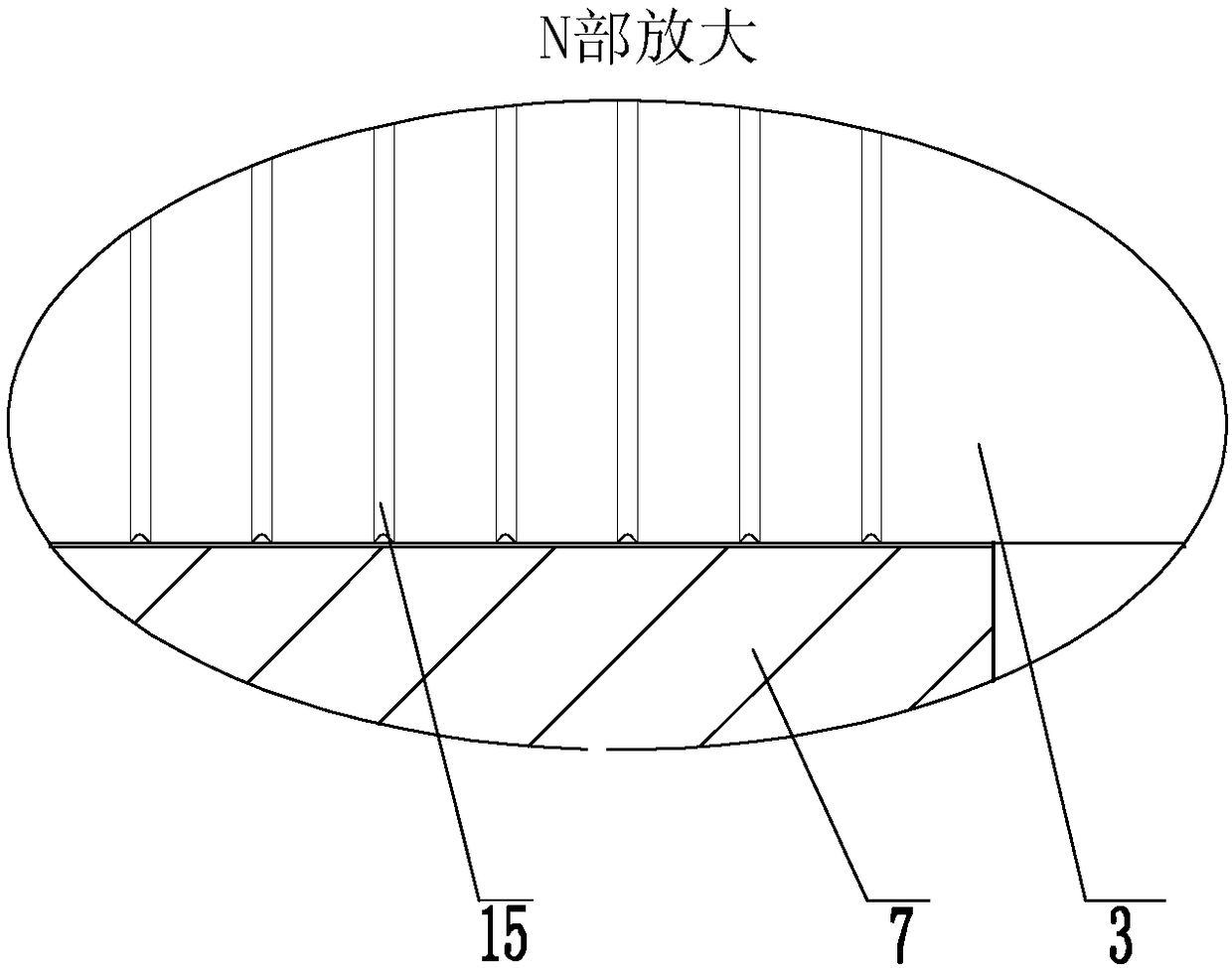
[0029] The present invention will be further described below with specific embodiments in conjunction with the drawings, see figure 1 — Figure 7 :

[0030] A rotary liquid supply device. The two ends of a hollow cylinder 17 are respectively connected with ring-shaped bearings 6, 9 seats 13. The inner walls of the bearings 6, 9 seats 13 are installed with bearings 6, 9 and the rotating shaft 3 is supported for rotation. On the inner rings of the bearings 6, 9, each bearing seat 13 and the outer ends of the bearings 6, 9 are provided with a sealing end cover 4, 10, and the rotating shaft 3 is provided with two axial liquid guide holes 31, 32 side by side. , Each liquid guide hole 31, 32 is provided with a radial liquid flow opening A1, B1 communicating with the liquid guide hole 31, 32, the cylinder 17 is provided with two annular grooves 171 at intervals, and each annular groove 171 Both are fitted with two floating sleeves 7 that are rotationally sealed with the rotating shaft ...


PUM


Abstract

The invention belongs to the technical field of rotating liquid supply and relates to a rotating liquid supply device. Bearing bases are connected to the two ends of a barrel body correspondingly. A bearing is installed on each bearing base. A rotating shaft is supported on the bearings. A sealing end cover is arranged at the outer ends of each bearing base and the corresponding bearing. Two axial liquid guiding holes are formed in the rotating shaft in parallel. Each liquid guiding hole is provided with a radial liquid passing opening. Two annular grooves are formed in the barrel body in a spaced mode. Each annular groove is internally sleeved with two floating sleeves. A spring is supported between the two floating sleeves in each annular groove. A radial liquid passing hole is formed in each annular groove. Each liquid passing hole communicates with the corresponding liquid passing opening. The floating sleeves and the barrel body are circumferentially positioned. Sealing rings are arranged between the barrel body and the bearing bases as well as between the bearing bases and the sealing end covers. A liquid collecting cavity is formed in the inner side of each bearing. Each bearing base is provided with a radial liquid drainage hole communicating with the corresponding liquid collecting cavity. The rotating liquid supply device is suitable for rotating shaft liquid passing hole liquid pressure conveying.

Description

Technical field [0001] The invention belongs to the technical field of rotary liquid supply, and particularly refers to a rotary liquid supply device. Background technique [0002] The hydraulic rotary joint is a device that outputs hydraulic oil medium to the hydraulic actuator on the rotating equipment. It is widely used in industrial equipment such as machinery, chemical industry, pharmaceuticals, etc., and requires different working conditions and uses for various industrial equipment, such as Rotation speed, pressure, flow, temperature, etc., currently used domestically for hydraulic rotary joints with a speed of more than 2000r / min and a pressure of 30MPa. The design is unreasonable from the structural point of view, and the processing accuracy requirements are too high. The outer diameter of the rotating joint and the rotating shaft are matched to form a seal. The gap is required to be between 0.01 and 0.018mm. The inner hole of the rotating joint and the bearing and shaft...

Claims


Application Information

Patent Timeline
Patent Type & Authority Patents(China)
IPC IPC(8): F16L39/06F16J15/16
CPCF16J15/16F16L39/06
Inventor 张嗣远
Owner 张嗣远
Why Eureka
Try Eureka