A vacuum suction blank structure and a feeding mechanism comprising the vacuum suction blank structure

A feeding mechanism and vacuum suction technology, applied in the field of feeding mechanism and vacuum suction blank structure, can solve the problems of rough texture, pattern damage, limited surface pattern, etc., to achieve smooth conveying process, improve production efficiency, and reduce pressing effect of times

Active Publication Date: 2019-02-26
GUANGDONG TIANBI CERAMICS
View PDF5 Cites 0 Cited by
  • Summary
  • Abstract
  • Description
  • Claims
  • Application Information

AI Technical Summary

Problems solved by technology

[0002] With the increasingly fierce competition in the building ceramics market, in order to expand the market share, most of the manufacturers increase the production capacity and enrich the patterns and colors of the products through continuous transformation of equipment, but the patterns of the micropowder products produced by them are generally unstable and the texture rough
Specifically, during the production and molding process of ceramic products, the existing ceramic tiles are generally sent into the molding press through a fidelity grid for pressing, but since the ceramic tiles are composed of granular powder, the fidelity The grid will inevitably vibrate during the conveying process, which will cause damage to the pattern on the ceramic tile, so that the pattern of the pressed ceramic product is not perfect; in addition, the pattern of the existing ceramic tile is not perfect. The method is limited, which in turn leads to the limitation of the surface patterns of the existing ceramic tiles

Method used


Image

  • A vacuum suction blank structure and a feeding mechanism comprising the vacuum suction blank structure
  • A vacuum suction blank structure and a feeding mechanism comprising the vacuum suction blank structure
  • A vacuum suction blank structure and a feeding mechanism comprising the vacuum suction blank structure

Examples


Embodiment Construction

[0015] The present invention will be further described below in conjunction with specific examples.

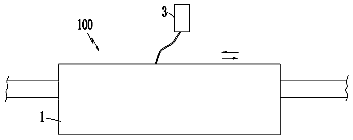
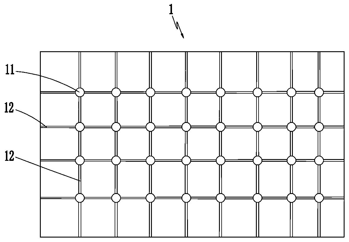
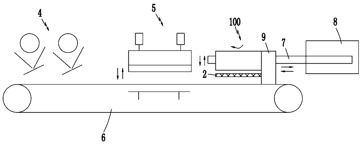
[0016] See attached figure 1 and 2 As shown, this embodiment provides a vacuum suction blank structure 100, which includes a vacuum suction mold 1 for absorbing ceramic tiles, a lifting drive cylinder (not shown in the figure) for driving the vacuum suction mold 1 to move up and down, and The vacuum generating device 3 used to make the vacuum suction mold 1 generate a vacuum air source, wherein the bottom end surface of the vacuum suction mold 1 is provided with a plurality of suction and exhaust grooves 12 arranged in a vertical and horizontal direction, and each pair of intersecting An air hole 11 communicating with the vacuum generating device 3 is provided at the intersection of the suction and exhaust grooves 12 . At the same time, in order to enable the vacuum suction blank structure 100 to drive the ceramic blank to rotate in the horizontal direction, it is also provi...


PUM


Abstract

The invention provides a vacuum blank adsorption structure which is simple in structure, low in cost, stable in work and capable of effectively ensuring stripes and patterns of a ceramic tile blank. The vacuum blank adsorption structure comprises a vacuum adsorption die used for adsorbing the ceramic tile blank, a lifting drive cylinder used for driving the vacuum adsorption die to rise and fall and a vacuum generation device used for enabling the vacuum adsorption die to generate a vacuum gas source. The bottom end face of the vacuum adsorption die is provided with a plurality of longitudinally and transversely formed air suction and exhaust grooves in an intersected mode. The intersection of each pair of intersected air suction and exhaust grooves is provided with an air hole communicating with the vacuum generation device. Compared with the prior art, according to the scheme, by adoption of the structural form, the traditional mode that a ceramic tile blank is conveyed into a press through a fidelity grating is changed, and the vacuum blank adsorption structural form in the scheme is utilized, and by adsorbing the ceramic tile blank through vacuum, it can be ensured that the blank is not prone to shaking in the transferring process, and the whole conveying process is stable.

Description

technical field [0001] The invention relates to the technical field of ceramic pattern forming equipment, in particular to a vacuum suction blank structure and a feeding mechanism comprising the vacuum suction blank structure. Background technique [0002] With the increasingly fierce competition in the building ceramics market, in order to expand the market share, most of the manufacturers increase the production capacity and enrich the patterns and colors of the products through continuous transformation of equipment, but the patterns of the micropowder products produced by them are generally unstable and the texture rough. Specifically, during the production and molding process of ceramic products, the existing ceramic tiles are generally sent into the molding press through a fidelity grid for pressing, but since the ceramic tiles are composed of granular powder, the fidelity The grid will inevitably vibrate during the conveying process, which will cause damage to the pa...

Claims


Application Information

Patent Timeline
Patent Type & Authority Patents(China)
IPC IPC(8): B28B5/00B28B5/02B28B3/00
CPCB28B3/00B28B5/00B28B5/021
Inventor 区秀芬
Owner GUANGDONG TIANBI CERAMICS
Why Eureka
Try Eureka