
Copper pipe drawing device

A drawing device, copper tube technology, applied in the direction of the mandrel, can solve the problems of low processing efficiency, inability to process extruded raw material tubes, etc., to achieve the effects of improving processing efficiency, increasing continuity, and accelerating heat dissipation

Inactive Publication Date: 2017-07-07
CHONGQING YONGCHUAN DISTRICT YIRUI MACHINERY
View PDF5 Cites 7 Cited by
  • Summary
  • Abstract
  • Description
  • Claims
  • Application Information

AI Technical Summary

Benefits of technology

Invention describes an apparatus that uses liquid (oil) or gas instead of rods during manufacturing processes. By pressing downward against the inside surface of the cylinder containing the raw materials being processed, it expands them without limiting their size. It then removes excessive moisture from these tubes while still keeping everything fixed together. Additionally, when used repeatedly over multiple times, there are fewer parts wearing out faster than other components due to increased resistance caused by repeated use. Overall, this technology allows for more efficient production of products made up of different types of materials compared to traditional methods like casting moldings.

Problems solved by technology

This patented technical problem addressed in this patents relates to improving the efficient use of drawings machines during production processes due to limitations associated with traditional methods like empty drafting and free standing casting techniques. These issues include wasteful consumption of resources caused by excessive machining time and difficulty in achieving desired dimensions within certain tolerances.

Method used


Image

  • Copper pipe drawing device

Examples


Embodiment Construction

[0020] The present invention will be described in further detail below by means of specific embodiments:

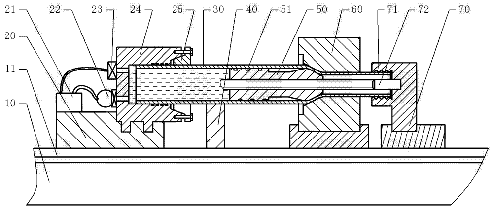
[0021] The reference signs in the drawings of the description include: base 10, slide rail 11, slide seat 20, hydraulic oil tank 21, hydraulic pump 22, pressure control valve 23, sealing cover 24, expansion sleeve 25, extruded raw material pipe 30, support Seat 40, mandrel 50, oil guiding groove 51, mold 60, traction mechanism 70, fixture 71, screw rod 72.

[0022] The embodiment is basically as figure 1 Shown:

[0023] The copper pipe drawing device of this embodiment includes a base 10, a mold 60, a mandrel 50, a traction mechanism 70 and a driving motor. The mold 60 is fixed on the base 10, and the mandrel 50 cooperates with the mold 60 to form a ring; the base 10 is provided with a slide rail 11, and the traction mechanism 70 is slidably connected to the slide rail 11, and the base 10 is also provided with Parallel to the rack of the slide rail 11, the traction mec...


PUM


Abstract

The invention relates to the field of machining and discloses a copper pipe drawing device. The copper pipe drawing device comprises a base, a die, a core rod, a traction mechanism and a drive motor. The die is fixed to the base. The core rod is matched relative to the die. A sliding rail is arranged on the base. The traction mechanism is connected to the sliding rail in a sliding manner, and a clamp is further arranged on the traction mechanism. The sliding rail is further provided with a sliding seat connected with the sliding rail in a sliding manner. A hydraulic oil tank, a hydraulic pump, a sealing cover and a pressure control valve are arranged on the sliding seat. One end of the sealing cover is an opening end, and the other end of the sealing cover is a fixed end fixed to the sliding seat, wherein the opening end is provided with a locking mechanism. The pressure control valve and the hydraulic pump are installed at the fixed end of the sealing cover and communicate with a cavity of the sealing cover. The sliding seat, the die and the traction mechanism are sequentially arranged on the base, and the opening end of the sealing cover is opposite to the die. The core rod of the copper pipe drawing device does not need to be fixed, and therefore the length of extrusion raw material pipes is not limited; and the device can be used for machining the long extrusion raw material pipes, and therefore the clamping times can be reduced, and the efficiency is improved.

Description


Claims


Application Information

Patent Timeline
Owner CHONGQING YONGCHUAN DISTRICT YIRUI MACHINERY
Learn More