Leg traction mechanism

A traction mechanism and leg technology, applied in the field of orthopedic traction equipment, can solve the problems of inconvenient dressing change, poor traction effect, difficult disassembly and adjustment of fixed sleeves, etc.

Inactive Publication Date: 2017-07-07
CHENGDU XUNDE SCI & TECH
View PDF2 Cites 0 Cited by
  • Summary
  • Abstract
  • Description
  • Claims
  • Application Information

AI Technical Summary

Problems solved by technology

[0003] The purpose of the present invention is to provide a leg traction mechanism, which solves the problem that the fixed sleeve of the common leg traction mechanism is not easy to disassemble and adjust, resulting in poor traction effect, and also solves the problem of inconvenient dressing change

Method used


Image

  • Leg traction mechanism
  • Leg traction mechanism

Examples


Embodiment Construction

[0014] Specific embodiments of the present invention will be described in detail below in conjunction with the accompanying drawings. It should be understood that the specific embodiments described here are only used to illustrate and explain the present invention, and are not intended to limit the present invention.

[0015] In the present invention, in the absence of a contrary description, the orientation words included in the term such as "top-down" only represent the orientation of the term in the normal use state, or the common name understood by those skilled in the art, should not be construed as a limitation of this term.

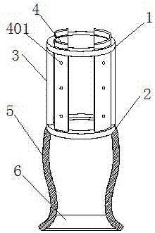
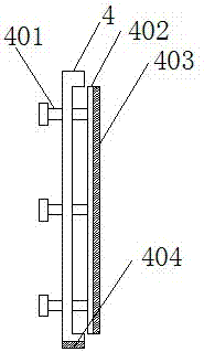
[0016] Such as figure 1 and figure 2 Shown: the present invention provides a leg traction mechanism, the leg traction mechanism includes a first collar 1 and a second collar 2 coaxially arranged from top to bottom, the first collar 1 and the The second ferrule 2 is connected by a strut 3 (one end of the strut 3 is connected to the circumferenti...


PUM


Abstract

The invention discloses a leg traction mechanism. The leg traction mechanism comprises a first sleeve loop and a second sleeve loop. The first sleeve loop and the second sleeve loop are connected via poles. The surface of the circumference of the first sleeve loop is provided with a plurality of through grooves. The surface of the upper circumference of the second sleeve loop is provided with a plurality of grooves. The leg traction mechanism also comprises fixing plates, one end of each fixing plate is at least partially positioned in the corresponding groove, and the other end of each fixing plate penetrates the corresponding through groove. A side surface of each fixing plate is inwardly recessed to form a long-strip groove in the length direction of the fixing plate, a pressing plate is disposed in each long-strip groove, and threaded holes penetrating the fixing plate are also disposed in the long-strip groove. One end of a locking screw is connected to each pressing plate, and the other end of the locking screw penetrates the corresponding threaded hole and extends to the outside of the corresponding fixing plate. The problem that the traction effect is not good due to the fact that fixing sleeves of a common leg traction mechanism are not easy to assemble, disassemble and adjust is solved, and the problem that medicine changing is inconvenience is also solved.

Description

technical field [0001] The present invention relates to orthopedic traction devices and, in particular, to leg traction mechanisms. Background technique [0002] Traction is a commonly used treatment method in orthopedics; leg traction frame is a common device for assisting traction, mainly to improve the traction effect of the leg. In the traditional leg traction mechanism, the fixed sleeve is not easy to disassemble, and the pressure of the fixed sleeve on each part of the leg is uneven and cannot be adjusted, resulting in low traction effect. The whole fixing sleeve needs to be taken off during the medicine, which makes it very inconvenient to change the medicine. Contents of the invention [0003] The purpose of the present invention is to provide a leg traction mechanism, which solves the problem that the fixed sleeve of the common leg traction mechanism is difficult to disassemble and adjust, resulting in poor traction effect, and also solves the problem of inconven...

Claims


Application Information

Patent Timeline
IPC IPC(8): A61F5/042
CPCA61F5/0102A61F5/042
Inventor 龚素华
Owner CHENGDU XUNDE SCI & TECH
Why Eureka
Try Eureka