Light-emitting structure and electronic equipment

A light-emitting structure and light-emitting area technology, applied in lighting and heating equipment, semiconductor devices of light-emitting elements, light sources, etc., can solve problems such as large thickness space, contrary to the development trend of thin and light electronic equipment, and affect the portability of electronic equipment. Achieve the effect of realizing thin and light structure

Inactive Publication Date: 2017-07-04
XIAOMI INC
View PDF6 Cites 0 Cited by
  • Summary
  • Abstract
  • Description
  • Claims
  • Application Information

AI Technical Summary

Problems solved by technology

[0003] However, the above-mentioned stacking structure needs to occupy a large thickness space, which is contrary to the development trend of thinner and lighter electronic equipment, and affects the portability of electronic equipment.

Method used


Image

  • Light-emitting structure and electronic equipment
  • Light-emitting structure and electronic equipment
  • Light-emitting structure and electronic equipment

Examples


Embodiment Construction

[0028] Reference will now be made in detail to the exemplary embodiments, examples of which are illustrated in the accompanying drawings. When the following description refers to the accompanying drawings, the same numerals in different drawings refer to the same or similar elements unless otherwise indicated. The implementations described in the following exemplary examples do not represent all implementations consistent with the present disclosure. Rather, they are merely examples of apparatuses and methods consistent with aspects of the present disclosure as recited in the appended claims.

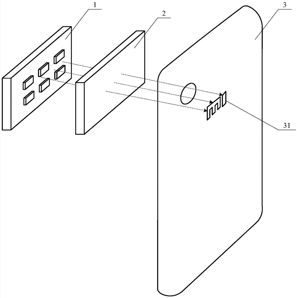
[0029] figure 1 is a schematic diagram of a light-emitting structure in the related art, such as figure 1 As shown, the light-emitting structure in the related art may include: a light source module 1 and a polarizing module 2; wherein, the light source module 1 and the polarizing module 2 are figure 1 The shown left and right directions are stacked and installed in the electronic de...


PUM


Abstract

The invention relates to a light-emitting structure and electronic equipment. The light-emitting structure can comprise a light source module and a polarization module. The polarization module contains a polarizer. The incident section of the polarizer faces the light source module so that light emitted out of the light source module can shoot into the polarizer through the incident section. The polarizer is arranged parallel to the incident light from the light source module and can guide the incident light to a preset light-emitting area on the polarizer. According to the technical scheme, the light-emitting effect can be achieved within a limited space, and the light and thin structure of the electronic equipment can be better obtained.

Description

technical field [0001] The present disclosure relates to the technical field of terminals, and in particular to a light emitting structure and electronic equipment. Background technique [0002] In the related art, it is necessary to stack structures such as light source modules and polarizing modules inside the electronic device to achieve the luminous effect on the surface of the housing of the electronic device. [0003] However, the above-mentioned stacking structure needs to occupy a relatively large thickness space, which is contrary to the development trend of thinner and lighter electronic equipment, and affects the portability of the electronic equipment. Contents of the invention [0004] The present disclosure provides a light emitting structure and an electronic device to solve the deficiencies in the related art. [0005] According to a first aspect of an embodiment of the present disclosure, there is provided a light emitting structure, comprising: [0006]...

Claims


Application Information

Patent Timeline
Patent Type & Authority Applications(China)
IPC IPC(8): F21S8/00F21V11/00F21V13/12F21Y115/10
CPCF21S8/00F21V11/00F21V13/12
Inventor 张斌高原靳宏志
Owner XIAOMI INC
Why Eureka
Try Eureka